Terminal block x2 connection, Ethernet connection, Electric lock connection – 2N Helios IP Vario User Manual
Page 24
24
1.
2.
3.
4.
Terminal Block X2 Connection
Terminal block X2 includes 10 terminals whose functions are distinguished by colour.
Terminals 5–10 are used for connecting
to the Ethernet.
2N
®
Helios IP Vario
Terminals 3–4 are designed for connecting the electric lock and terminals 1–2 help
connect an external 12V / 2A DC power supply if no PoE power supply is available.
The terminal block is included in the package. To adjust an already installed 2N
®
, disconnect it IP from the power supply. Then pull to remove
Helios IP Vario
the terminal block from the printed circuit board.
Insert the wires under the respective terminals.
Tighten the terminals using a flat screwdriver.
Replace the terminal block to the printed circuit board.
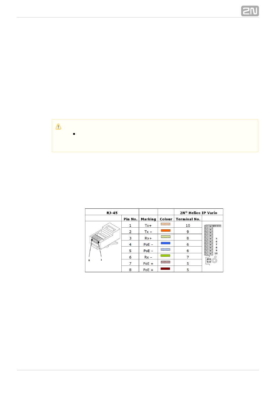
Ethernet Connection
For the connections and meanings of the wires see the table below. Join UTP cable
wires 4 (blue) and 5 (white-blue) and attach them under terminal 6 on 2N
®
Helios IP
In the same way, join wires 7 and 8 and place them under terminal 5 of
Vario
2N
®
.
Helios IP Vario
Table 2.1 Terminal Block Connections
Electric Lock Connection
The electric lock can be connected to terminals 3 and 4 of terminal block X2.
Caution
Make sure that the cables leading through the 2N
®
Helios IP Vario
cover bottom groove are installed properly. For the correct installation of
the cables refer to Figure 2.7.