2 electric installation, Description of printed circuit board connectors – 2N Helios IP Vario User Manual
Page 22
22
2.2 Electric Installation
2N
®
Helios IP Vario is designed for connection in the Ethernet computer network
(10/100BASE-T) using a UTP cable. Use a CAT 5e UTP cable at least for connection.
is fed through the PoE (Power over Ethernet) technology. No
2N
®
Helios IP Vario
additional cabling is therefore necessary. If your Ethernet is not equipped with the PoE
technology, it is possible to use a PoE injector, Part No. 91378100. As an alternative,
you can use a power adapter, Part No. 91341481E.
is configured
2N
®
Helios IP Vario
over an integrated administration web server, which can be controlled from any web
browser, e.g., Mozilla Firefox.
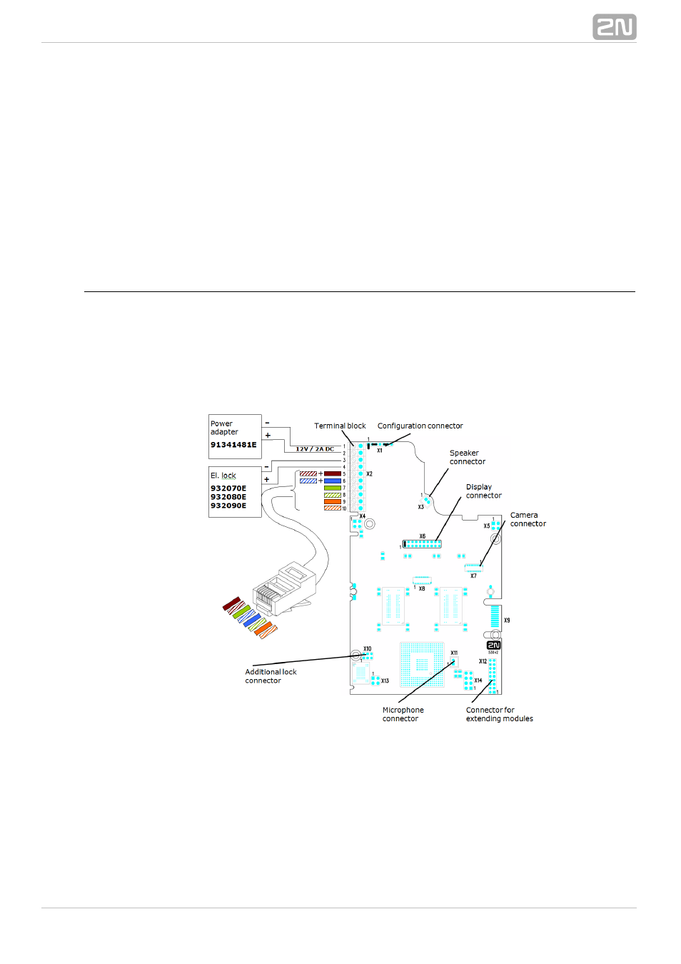
Description of Printed Circuit Board Connectors
In
you can see the location of the printed circuit board (PCB) connectors.
Figure 2.11
Connectors to which the accessories can be connected and connectors that serve for
configuring
are indicated on the board. The UTP cable for the
2N
®
Helios IP Vario
Ethernet connection is to be connected to the terminal block X2 as shown in
.
Table 2.1
The terminal block can be removed from the PCB. The connection of each of the
connectors is described in the subsections below.
Figure 2.11 Description of Connectors, PCB Version 530v2
- Analogue GSM gateway 2N EasyGate - Manual, 1575 v1.1.0.2 (69 pages)
- Fixed line replacement with 2N EasyGate - Quick Start, 1129 v1.5E (2 pages)
- Fixed line replacement with 2N EasyGate PRO - Quick Start, 1711 v1.01 (2 pages)
- Analogue GSM gateway 2N EasyGate PRO - Manual, 1749 v1.03 (79 pages)
- Fixed line replacement with 2N EasyGate PRO UMTS - Quick Start, 2018 v1.00 (2 pages)
- Analogue UMTS gateway 2N EasyGate UMTS USB - Quick Start (9 pages)
- Analogue UMTS gateway 2N EasyGate UMTS USB - User Manual, v1.00 (38 pages)
- Wireless 3G router 2N EasyRoute_old design - Quick start, 1526 v2.00 (2 pages)
- Wireless 3G router 2N EasyRoute_new design - Quick start, 1664 v1.00 (2 pages)
- Wireless 3G router 2N EasyRoute_new design - User manual, 1670 v1.06 (101 pages)
- Wireless 3G router 2N EasyRoute_old design - User manual, 1571 v1.06 (99 pages)
- Entrance guard 2N Helios - Manual - antivandal installation (2 pages)
- Design intercom 2N Helios - Guide mounting (2 pages)
- Door camera for 2N Helios - Installation manual - camera 9135210E (2 pages)
- Home intercom 2N Helios - Manual - display installation (5 pages)
- Electric lock for 2N Helios - Secondary switch - installation manual, 1360 v2.0 (2 pages)
- Door intercom 2N Helios - Manual, 1322 v3.0 (76 pages)
- Helios IP User manual, 1510 v1.13 (143 pages)
- Helios IP User manual, 1510 v1.12 (127 pages)
- Helios IP User manual, 1510 v1.11 (119 pages)
- Lift emergency phone 2N LiftNet - Manual, 1446 v1.8.3 (97 pages)
- Mobile Audio Gateway public address system - Quick start manual (2 pages)
- IVR Editor manual v1.0.2 (43 pages)
- Omega Lite PBX Assistant - manual v1.2 (57 pages)
- Omega series - Configuration Tool manual v1.10 (114 pages)
- IVR Editor manual v1.0 (43 pages)
- Omega series - Configuration Tool manual v1.9 (114 pages)
- Omega series - VoIP manual v1.4 (113 pages)
- Omega 48 - Basic Services v1.0 (60 pages)
- Omega 48 - Installation Manual v1.0 (48 pages)
- Omega 48 - Operator Services v1.0 (48 pages)
- StarPoint 500 - manual v2.0 (32 pages)
- Omega Lite - Configuration Tool manual v1.6 (101 pages)
- Omega Series - Voicemail v1.0 (31 pages)
- Omega Lite - Installation Manual v1.9 (58 pages)
- Omega Lite - Configuration Tool manual v1.8 (112 pages)
- Omega Lite - Configuration Tool manual v1.7 (112 pages)
- Omega Series - Basic Services (60 pages)
- Omega Lite - Installation Manual v1.5 (53 pages)
- Omega Series - Operator Services (48 pages)
- Omega Lite Panel - manual v1.0 (34 pages)
- Omega Lite PBX Assistant - manual v1.0 (49 pages)
- Omega Lite - Quick Guide v1.0 (1 page)
- Omega Series - VoIP manual v1.2 (88 pages)
- Lift emergency phone 2N SingleTalk - Manual, 1514 v6.3.0 (73 pages)