Axle lockout cylinder, Axle lockout cylinder -28 – JLG 4394RT Service Manual User Manual
Page 97
SECTION 3 - CHASSIS, PLATFORM & SCISSOR ARMS
3121249
– JLG Lift –
3-61
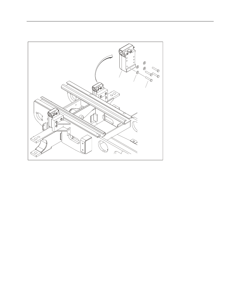
Axle Lockout Cylinder
REMOVAL:
1. Disable machine operation.
2. Disconnect, cap and label hydraulic lines on the axle
lockout cylinder (1).
3. Remove the four bolts (2) and washers (3) connect-
ing the cylinder to the frame.
4. Carefully remove cylinder from the frame.
INSTALLATION:
1. Attach cylinder to frame using four bolts (2) and
washers (3).
NOTE: Apply Loctite® #242 and Loctite® Primer #7471 to
bolts (2).
2. Uncap and reconnect hydraulic lines to cylinder.
NOTE: Refer to Section 4.13, Cylinder Assemblies for axle
lockout cylnder breakdown and bleeding procedure.
3. Operate axle lockout cylinder function to ensure
proper functioning.
1
2
3
1. Axle Lockout Cylinder
2. Bolt, 1/2"-11NC x 2 3/4"
3. Washer
Figure 3-35. Axle Lockout Cylinder