JLG 4394RT Service Manual User Manual
Page 194
SECTION 4 - HYDRAULICS
4-28
– JLG Lift –
3121249
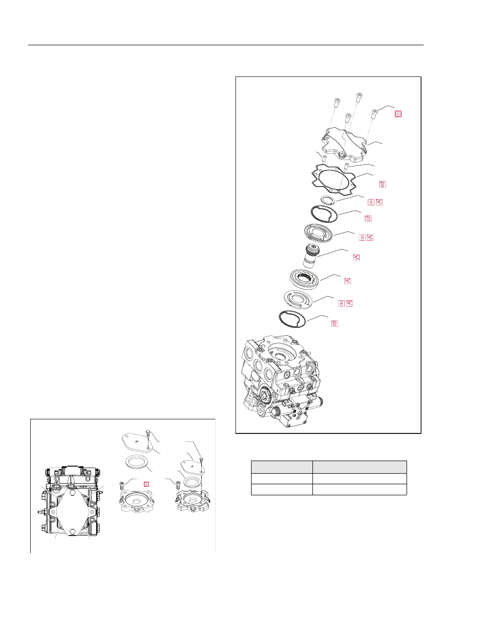
8. Remove the charge pump outer ring (S150), and
gearset (S100).
9. Remove valve plate (S250) with seal (S300). Discard
seal
INSPECTION:
10. Inspect the components for wear, scratches or pit-
ting. Carefully inspect the valve and pressure-bal-
ance plates. Scratches on these components will
cause a loss of charge pressure. If any component
shows signs of wear, scratching or pitting, replace it.
REASSEMBY:
11. Install new seals (S300) in the valve (S250) and
pressure-balance (S200) plates.
12. Install valve plate (S250) in the same orientation as
removed.
13. Lubricate and install charge pump (S100) and outer
ring (S150).
14. Install charge pump coupling (K200).
15. Install pressure balance plate (S200) in the same ori-
entation as removed.
16. Install the thrust washer (K500). Coated side goes
toward charge pump coupling (K200).
17. Install a new cover gasket. (K150). If removed, install
guide pins (K450).
18. Install the auxiliary pad or charge pump cover and
cap screws. Using a 10mm internal hex wrench,
torque the cap screws (K400) to 68 lb-ft (92 Nm).
Torque in sequence below.
19. Reinstall auxiliary pump or pad seal (K250) and
shipping cover (K300).
.
SAE B
SAE A
K400
8 mm
K300
K350
(see table)
K250
Auxilliary pads
1
2
3
4
Torque sequence
Cover Screw K350
Cover Pad
Wrench Size; Torque
A
17 mm; 35 lb-ft (48 Nm)
B, C
19 mm; 58 lb-ft (77 Nm)
K500
S100
S300
S200
K200
K150
K400
8 mm
K100
S300
S250
G450
G450
Charge pump removal/installation