5 drive pump start-up procedure, Drive pump start-up procedure -8, Cylinder piston nut torque specifications -8 – JLG 4394RT Service Manual User Manual
Page 174: Holding valve torque specifications -8
SECTION 4 - HYDRAULICS
4-8
– JLG Lift –
3121249
24. Prior to setscrew installation spot drill rod before
installing the setscrew(s) which secure the piston
attaching nut to the diameter groove.
25. Remove the cylinder rod from the holding fixture.
26. Position the cylinder barrel in a suitable holding fix-
ture.
EXTREME CARE SHOULD BE TAKEN WHEN INSTALLING THE
CYLINDER ROD, HEAD, AND PISTON. AVOID PULLING THE ROD
OFF-CENTER, WHICH COULD CAUSE DAMAGE TO THE PISTON
AND CYLINDER BARREL SURFACES.
27. With barrel clamped securely, and while adequately
supporting the rod, insert the piston end into the
barrel cylinder. Ensure that the piston loading o-ring
and seal ring are not damaged or dislodged.
28. Continue pushing the rod into the barrel until the cyl-
inder head gland can be inserted into the barrel cyl-
inder.
29. If applicable, secure the cylinder head retainer using
a suitable chain wrench.
30. After the cylinder has been reassembled, the rod
should be pushed all the way in (fully retracted) prior
to the reinstallation of any holding valve or valves.
31. If applicable, install the cartridge-type holding valve
and fittings in the port block using new o-rings as
applicable. Refer to Table 4-2, Holding Valve Torque
Specifications.
4.5 DRIVE PUMP START-UP PROCEDURE
THE FOLLOWING PROCEDURE SHOULD ALWAYS BE PER-
FORMED WHEN STARTING A NEW PUMP OR WHEN RESTARTING
AN INSTALLATION IN WHICH EITHER THE PUMP OR MOTOR
HAVE BEEN REMOVED FROM THE SYSTEM.
THE FOLLOWING PROCEDURE SHOULD ALWAYS BE PER-
FORMED WHEN STARTING A NEW PUMP OR WHEN RESTARTING
AN INSTALLATION IN WHICH EITHER THE PUMP OR MOTOR
HAVE BEEN REMOVED FROM THE SYSTEM.
THE FOLLOWING PROCEDURE MAY REQUIRE THE MACHINE TO
BE DISABLED (WHEELS RAISED OFF THE GROUND, DRIVE
FUNCTION DISCONNECTED, ETC.) WHILE PERFORMING THE
PROCEDURE IN ORDER TO PREVENT INJURY TO TECHNICIAN
AND OTHER PERSONNEL. TAKE NECESSARY SAFETY PRECAU-
TIONS BEFORE MOVING THE MACHINE.
Prior to installing pump and/or motor, inspect unit(s) for
damage incurred during shipping and handling. Make
certain all system components (reservoir, hoses, valves,
fittings, heat exchanger, etc.) are clean prior to filling with
hydraulic fluid.
Fill reservoir with recommended hydraulic fluid, which
should be passed through a 10 micron (nominal, no
bypass) filter prior to entering the reservoir. The use of
contaminated fluid will cause damage to components,
which may result in unexpected machine movement.
The inlet line leading from the reservoir to the pump
should be filled prior to start-up. Check inlet line for prop-
erly tightened fittings and make sure it is free of restric-
tions and air leaks.
Be certain to fill pump and/or motor housing with clean
hydraulic fluid prior to start-up. Fill housing by pouring fil-
tered oil into upper case drain port.
Install a 0 to 500 psi (0 to 35 bar) pressure gauge in the
charge pressure gauge port to monitor charge pressure
during start-up.
It is recommended that the external control input signal
electrical connections be disconnected at the pump con-
trol until after initial start-up. This will allow the pump to
remain in its neutral position.
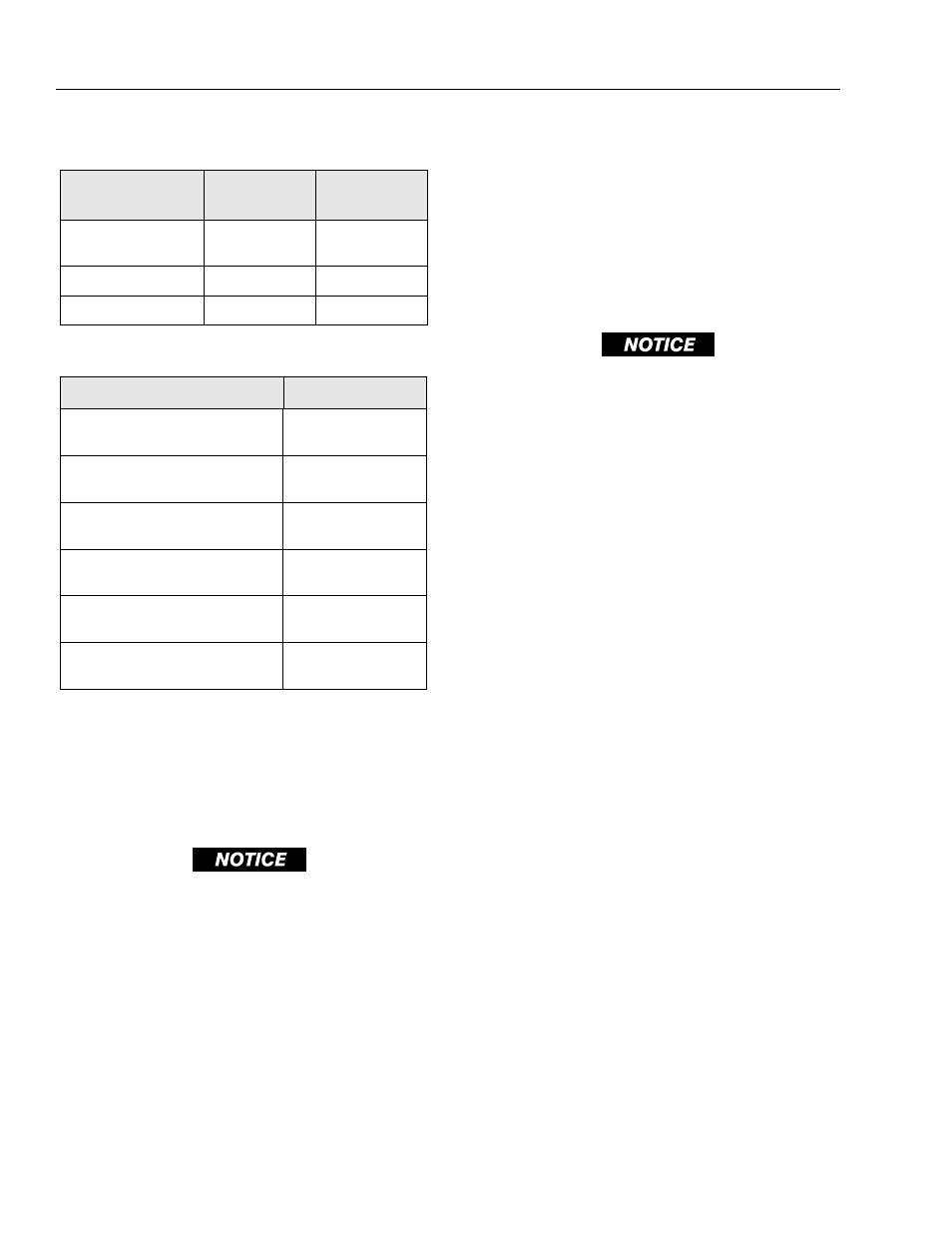
Table 4-1. Cylinder Piston Nut Torque Specifications
Description
Nut Torque Value
Setscrew torque
Value
Lift Cylinder
400 lb-ft
(542 Nm)
100 in.lbs.
(12 Nm)
Lockout Cylinder
N/A
N/A
Steer Cylinder
N/A
N/A
Table 4-2. Holding Valve Torque Specifications
Description
Torque Value
Sun - 7/8 hex M20 x 1.5 thds
30 - 35 lb-ft
(41 - 48 Nm)
Sun - 1-1/8 hex 1 - 14 UNS thds
45 - 50 lb-ft
(61 - 68 Nm)
Sun - 1-1/4 hex M36 x 2 thds
150 - 153 lb-ft
(204 - 207 Nm)
Racine - 1-1/8 hex 1-1/16 - 12 thds
50 - 55 lb-ft
(68 - 75 Nm)
Racine - 1-3/8 hex 1-3/16 - 12 thds
75 - 80 lb-ft
(102 - 109 Nm)
Racine - 1-7/8 hex 1-5/8 - 12 thds
100 - 110 lb-ft
(136 - 149 Nm)