Generator, Generator (gm engine) -66, Generator specifications -66 – JLG 4394RT Service Manual User Manual
Page 135
SECTION 3 - CHASSIS, PLATFORM & SCISSOR ARMS
3121249
– JLG Lift –
3-99
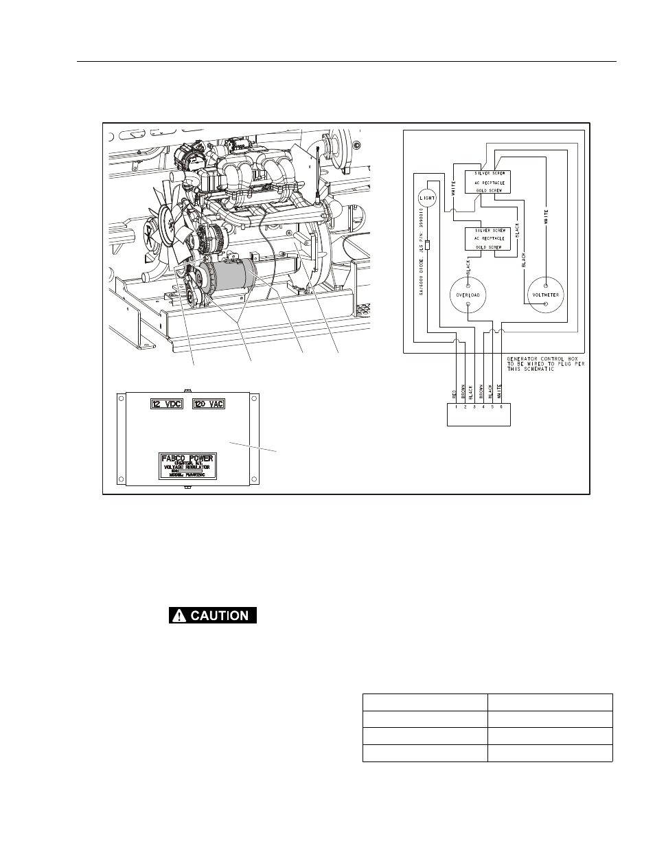
Generator
ALLOW ENGINE AND COMPONENTS TO COOL DOWN BEFORE
SERVICING.
REMOVAL:
1. Disable machine operation. Disconnect and label
electrical wires attached to generator (1).
2. Remove the generator from the engine (2) by remov-
ing the three bolts (3, 5) and washers (4, 5).
3. Replace belt if worn or damaged.
INSTALLATION:
1. Follow Removal Steps in reverse. Ensure belt is tight
before securing generator with the bolts.
NOTE: Apply Loctite® #242 to the bolts (3, 5).
1
2
7
5, 6
3, 4
1. Generator
2. GM Engine
3. Bolt, 5/16"-18NC x 1 1/4"
4. Washer
5. Bolt,7/16"-14NC x 1 1/4"
6. Washer
7. Voltage Regulator
Figure 3-71. Generator (GM Engine)
Table 3-14. Generator Specifications
Voltage
120V
Continuous
3.5 KW
Peak
4.5 KW
Amps Peak
37 Amps