JLG 4394RT Service Manual User Manual
Page 76
SECTION 3 - CHASSIS, PLATFORM & SCISSOR ARMS
3-40
– JLG Lift –
3121249
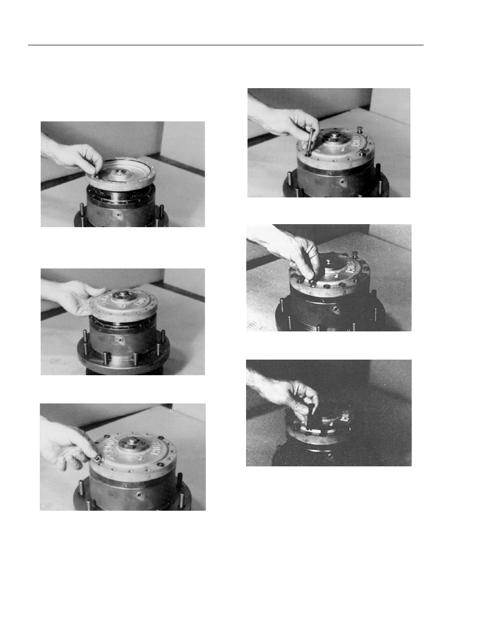
16. Set the cover (6A) on table, interior side up. Grease
o-ring (5) and place it into the counterbore around
the edge of cover (6A).
NOTE: The o-ring may be stretched or pinched together to
make it fit the counterbore exactly.
17. Place cover sub-assembly (6) onto ring gear (4),
aligning the pipe plug holes according to the align-
ment prior to disassembly.
18. Place four flatwashers (16) on top of the bolt holes in
the cover sub-assembly.
19. Place shoulder bolts (13) into the four shoulder bolt
holes in cover (6) and tighten by hand.
20. Place the remaining 12 flatwashers (16) onto the
remaining bolt holes in cover (6).
21. Place the 12 bolts into the remaining bolt holes in
cover (6) and tighten.