Axle assembly, Axle assembly -27 – JLG 4394RT Service Manual User Manual
Page 95
SECTION 3 - CHASSIS, PLATFORM & SCISSOR ARMS
3121249
– JLG Lift –
3-59
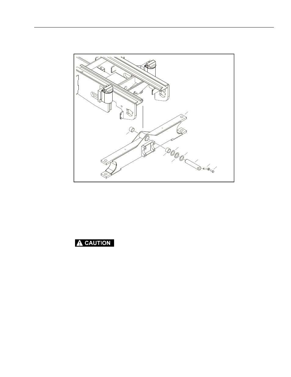
Axle Assembly
REMOVAL:
SUPPORT THE FRAME AND AXLE BEFORE ATTEMPTING ANY
REMOVAL AND/OR ASSEMBLY PROCEDURES.
1. Disable machine operation. Remove wheel and
drive assemblies (refer to Figure 3-1., Drive Assem-
bly (Bosch Rexroth )).
2. Remove the bolt (2) and pin keeper (3).
3. Push the axle pivot pin (4) out and remove the thrust
washers (5, 6) and bearings (7).
4. Axle can now be moved away from the frame.
ASSEMBLY:
1. When installing the axle assembly, follow Removal
Steps in reverse.
NOTE: Apply Loctite® #271 to bolt (2).
1
2
3
4
5
5
6
7
7
1. Front Axle
2. Bolt, 5/8"-11NC x 1 1/2"
3. Pin Keeper
4. Axle Pivot Pin
5. Thrust Washer
6. Thrust-Axle Washer
7. Bearing
Figure 3-33. Axle Assembly
This manual is related to the following products: