Loop flushing valve – JLG 4394RT Service Manual User Manual
Page 80
SECTION 3 - CHASSIS, PLATFORM & SCISSOR ARMS
3-44
– JLG Lift –
3121249
INSPECT THE COMPONENTS
Inspect the new seal, the motor housing seal bore, and
the sealing area on the shaft for rust, wear, and contami-
nation. Polish the shaft and clean the housing if neces-
sary.
INSTALLATION
1. Cover the shaft splines with an installation sleeve to
protect the shaft seal during installation.
2. Install a new shaft seal with the cupped side facing
the motor. Press seal into housing until it bottoms
out. Press evenly to avoid binding and damaging
the seal.
3. Install seal support washer.
4. Install snap ring.
5. Remove the installation sleeve.
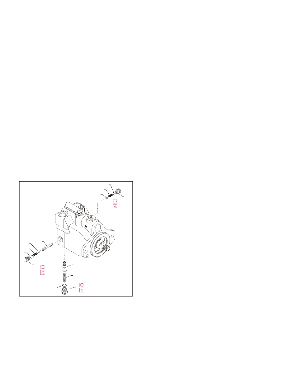
Loop Flushing Valve
REMOVAL
1. Using a 11/16 in internal hex wrench, remove plug
(1) and (2).
2. Using a 1/4 in hex wrench, remove plug (3).
3. Remove O-rings (4, 5, and 6).
4. Using pliers, remove centering springs (7, 8, and 9).
5. Remove spring retaining washers (10 and 11).
6. Remove shift spool (12).
7. Remove orifice poppet (13).
INSPECT THE COMPONENTS
Inspect new O-rings and the sealing area for rust, wear, or
contamination. Also check springs and poppet for wear.
INSTALLATION
1. Install orifice poppet (13).
2. Install shift spool (12).
3. Install spring retaining washers onto springs (10 and
11).
4. Carefully install centering springs (7, 8, and 9).
5. Install new O-rings (6, 4, and 5).
6. Using a 1/4 in hex wrench, torque plug (3) to 20 ft.
lbs. (27 Nm).
7. Using a 11/16 in internal hex, torque plugs (2 and 1)
to 27 ft. lbs. (37 Nm).
2
6
9
11
1
4
8
10
12
5
3
7
13
(37 Nm)
27 ft.lbs.
11/16 in
(37 Nm)
27 ft.lbs.
11/16 in
(27 Nm)
20 ft.lbs.
5/8 in
1. Plug
2. Plug
3. Plug
4. O-ring
5. O-ring
6. O-ring
7. Spring
8. Spring
9. Spring
10. Washer
11. Washer
12. Shift Spool
13. Orifice Poppet
Figure 3-11. Loop Flushing Spool