Main assembly – JLG 4394RT Service Manual User Manual
Page 73
SECTION 3 - CHASSIS, PLATFORM & SCISSOR ARMS
3121249
– JLG Lift –
3-37
9. Place spacer (1H) onto spindle (1A) in hub (1G).
NOTE: Make sure the retaining ring is securely seated in the
groove.
10. Place retaining ring (1I) over the spacer onto spindle
(1A) in hub (1G).
11. At this point the hub-spindle sub-assembly is com-
plete.
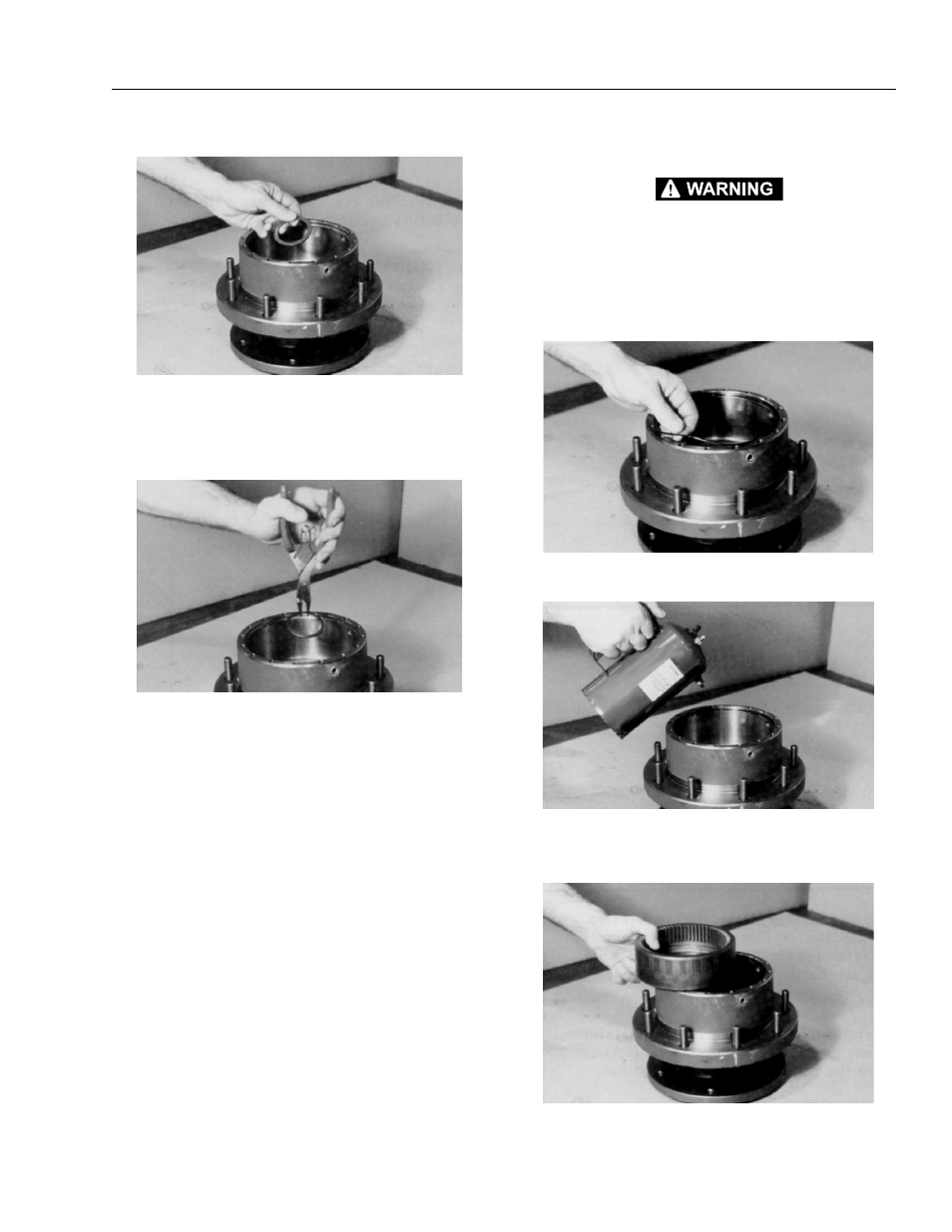
Main Assembly
BEWARE OF SHARP EDGES IN COUNTERBORE WHEN INSTALL-
ING THE O-RING
1. Grease o-ring (5) and place it into the counterbore in
hub (1G).
NOTE: O-ring may be stretched or pinched together to make
it fit the counterbore exactly.
2. Oil all exposed surfaces inside hub (1G).
3. Place internal gear (2) into hub (1G) so that its inter-
nal splines mesh with the external splines of spindle
(1A). Oil internal gear (2).
This manual is related to the following products: