Cover sub-assembly – JLG 4394RT Service Manual User Manual
Page 70
SECTION 3 - CHASSIS, PLATFORM & SCISSOR ARMS
3-34
– JLG Lift –
3121249
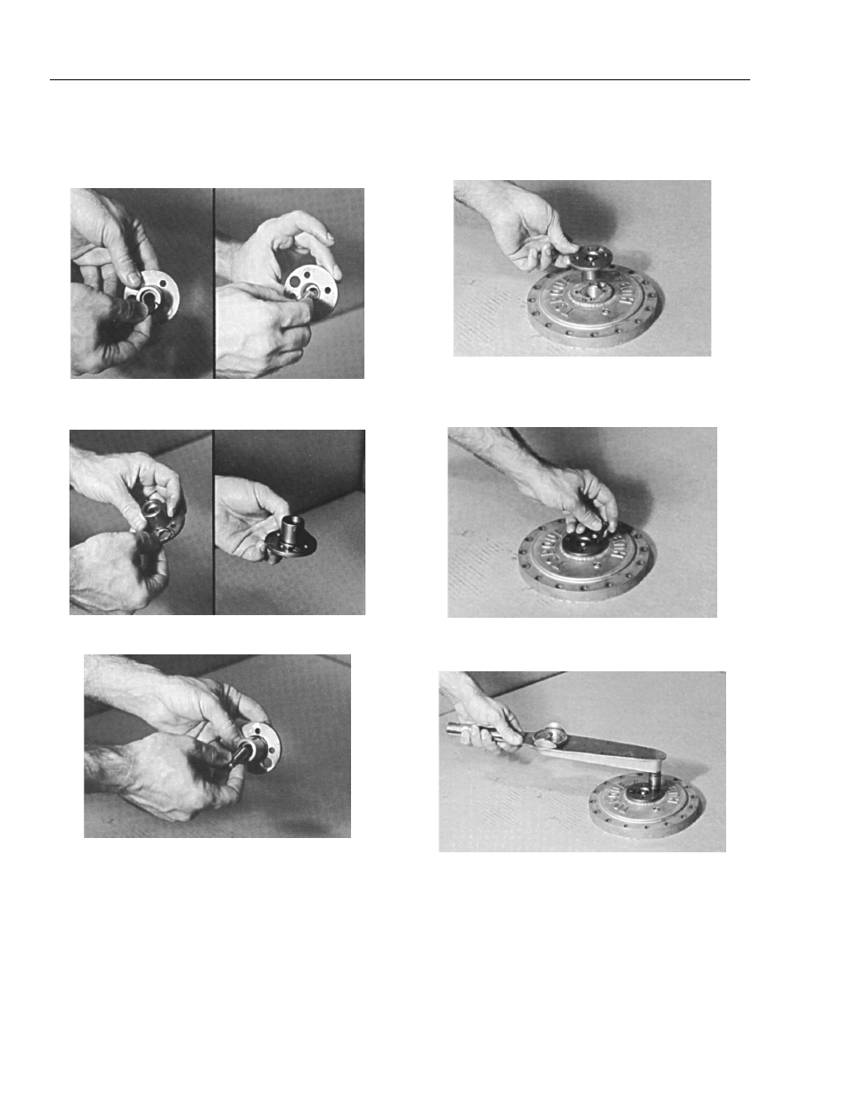
Cover Sub-Assembly
1. Using the disconnect rod, push o-ring (6F) into the
groove inside the cover cap (6B).
2. Place the o-ring (6G) onto the cover cap (6B) so that
it rests against the flange of the cover cap.
3. Insert disconnect rod (6E) into cover cap (6B).
4. Set cover (6A) on table, exterior side up. Place cover
cap (6B) onto cover (6A), aligning the pipe plug hole
in the cover cap over the pipe plug hole in the cover.
5. Place two of the cover cap bolts (6C) into any two
bolt holes that are 180° apart on the cover cap (6B)
and tighten bolts.
6. Using a torque wrench, apply 2.95 to 3.69 ft. lbs. (4
to 5 Nm) of torque to both bolts (6C).
This manual is related to the following products: