Cover disassembly, Carrier disassembly, Assembly of the carrier – JLG 4394RT Service Manual User Manual
Page 68
SECTION 3 - CHASSIS, PLATFORM & SCISSOR ARMS
3-32
– JLG Lift –
3121249
8. Turn hub (1G) over onto its small end. Remove two
pipe plugs (1J) from the two pipe plug holes in the
side of hub.
NOTE: If the unit does not have studs, skip this step:
9. Press the nine studs (1N) out of the stud holes in
hub (1G).
10. At this point the hub-spindle disassembly is com-
plete.
Cover Disassembly
1. Remove the two bolts (6C) holding disconnect cap
(6D) to cover (6A).
2. Remove disconnect cap (6D) from top of cover cap
(6B) and cover (6A).
3. Remove the two bolts (6C) attaching cover cap (6B)
to cover (6A).
4. Remove cover cap (6B) from cover (6A).
5. Remove disconnect rod (6K) from cover cap (6B).
6. Pry o-ring (6F) out of the groove inside cover cap
(6B). Discard the o-ring.
7. Remove o-ring (6G) from the flange of cover cap
(6B). Discard the o-ring.
8. Remove pipe plug (6H) from cover (6A).
9. At this point the cover disassembly is complete.
Carrier Disassembly
NOTE: When removing the needle rollers from the cluster
gears, discard the old needle rollers and use new
ones during re-assembly.
1. Using a punch and hammer, drive roll pin (3G) into
planet shaft (3E).
NOTE: Be sure to drive the roll pin all the way into the planet
shaft. Failure to do so could result in damage to the
carrier when removing the planet shaft from the car-
rier.
2. Using a punch and hammer, drive the planet shaft
(3E) out of the planet shaft hole in the carrier hous-
ing (3A).
3. When removing the planet shaft (3E) from the carrier
housing, one thrust washer (38), one cluster gear
(3F), and one more thrust washer will come off of the
planet shaft and come to rest inside the carrier.
Remove these parts from inside the carrier.
4. Remove 16 needle rollers (3C) from inside one end
of cluster gear (3F). Discard the needle rollers.
5. Remove one spacer (3D) from inside cluster gear
(3F).
6. Remove the remaining 16 needle rollers (3C) from
the other side of cluster gear (3F). Discard the nee-
dle rollers.
7. Repeat steps 1-6 to remove and disassemble the
two remaining cluster gears.
8. At this point the carrier disassembly is complete.
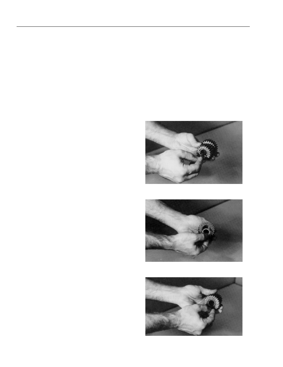
Assembly of the Carrier
1. Apply grease to the inside of one cluster gear (3F)
and line one half of cluster gear with 16 needle roll-
ers (3C).
2. Place one spacer (3D) inside cluster gear (3F) so
that it rests on top of the needle rollers.
3. Line the remaining half of cluster gear (3F) with 16
needle rollers.