Shaft seal, roller bearing & shaft replacement, Charge pump, Positioning seal in seal carrier – JLG 4394RT Service Manual User Manual
Page 193
SECTION 4 - HYDRAULICS
3121249
– JLG Lift –
4-27
6. Install solenoid with three cap screws (D050) using a
4 mm internal hex wrench. Torque screws to 5 Nm (4
lb-ft).
7. Install coil using a 12 point 26 mm socket. Torque
coil nut to 3.7 lb-ft (5 Nm).
8. Reconnect electrical connections and test the pump
for proper operation.
Shaft Seal, Roller Bearing & Shaft
Replacement
NOTE: The shaft assembly is serviceable without disassem-
bling the pump. Orient the pump on the work surface
so the shaft is pointing to the side.
REMOVAL:
1. Unwind the spiral ring (J300) from the housing to
release the shaft/seal/bearing subassembly.
2. Pry on the lip of the seal carrier (J275) to dislodge it
from the pump. Remove the seal carrier. Remove
and discard O-ring (J260). Press the seal (J250) out
of the carrier and discard.
3. Pull the shaft (J100) with bearing (J150) out of the
pump. If necessary, tap lightly on the shaft to dis-
lodge it from the cylinder block.
4. Remove the retaining ring (J200) using retaining ring
pliers. Press the bearing off the shaft.
INSPECTION:
5. Inspect the shaft journals for wear, scratching, and
pits. Check the splines for fretting; replace if dam-
aged. Rotate the bearing, if it does not rotate
smoothly, replace it.
REASSEMBLY:
6. Press the bearing (J150) onto the shaft (J100) and
replace the retaining ring (J200). Ensure the retain-
ing ring diameter is less than 1.53 in (38.84 mm)
when installed on the shaft.
7. Install the shaft/bearing assembly into the pump.
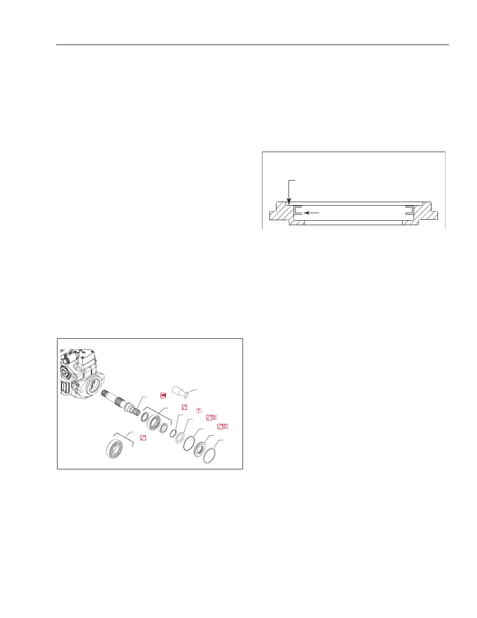
8. Lubricate and install a new O-ring (J260) onto seal
carrier (J275). Press a new seal (J250) into the seal
carrier. Press the seal until it is flush within 0.005 in
(+0.12mm ) or 0.0028 in (-0.72 mm) of the inside lip
of the carrier: see illustration.
9. Cover the shaft with a protective sleeve while install-
ing the seal carrier. Hand press the seal carrier into
the housing. Ensure the seal carrier clears the spiral
ring groove in the housing. Remove the protective
sleeve.
10. Wind the spiral ring into the housing. Ensure the
inside diameter of the spiral ring is greater than
2.677 in (68 mm) after installation.
Charge Pump
If the pump has an auxiliary pump attached, remove the
auxiliary pump and connecting shaft before removing the
auxiliary pad.
REMOVAL:
1. Position pump so end cover or auxiliary pad is on
top.
2. If necessary, remove auxiliary pump (not shown), or
shipping cover (K300) and pad seal (K250) as
shown on following page.
3. Remove end cover/auxiliary pad screws (K400)
using a 10 mm internal hex wrench.
NOTE: Alignment pins (G450) are in end cover. They may
dislodge during disassembly.
4. Remove and discard gasket (K150).
5. Remove thrust washer (K500). Note thrust washer
orientation.
6. Use a small hook to remove pressure balance plate
(S200) and seal (S300). Note plate orientation. Dis-
card seal.
7. Remove coupling (K200). Use a small hook if neces-
sary.
Shaft assembly
J150
J100
J200
J250
J260
J275
J300
J150
Protective
sleeve
Seal
Press flush to this surface
0.005 in +0.12 mm) 0.028 in -0.72 mm)
(
/
(
Positioning seal in seal carrier