16 drive torque hub, Disassembly, Drive torque hub -21 – JLG M4069 ANSI Service Manual User Manual
Page 93: Control valve -21, 16 drive torque hub disassembly
SECTION 4 - HYDRAULICS
3121122
– JLG Lift –
4-21
4.16 DRIVE TORQUE HUB
Disassembly
1. Loosen all cover bolts and drain oil from unit.
2. Remove the cover bolts and lift off input cover.
Remove and discard o-ring from counterbore of
input cover.
3. Remove sun gear and thrust washer.
4. Lift out the carrier and thrust washer.
5. Remove input spacer.
6. Lift out internal gear and thrust washer.
7. While wearing eye protection, remove the retaining
ring from the output shaft and discard.
8. Remove thrust washer from the output shaft.
9. The output shaft may now be pressed out of the
housing.
10. The bearing cups will remain in hub as will the inner
bearing cone. The outer bearing cone will remain on
the output shaft. The lip seal will be automatically
removed during this procedure.
NOTE: If bearing replacement is necessary, the bearing
cups can be removed with a slide hammer puller or
driven out with a punch.
11. To remove the cluster gears from the carrier, drive
the roll pin into the planet shaft. The planet shaft
may now be tapped out of the carrier. After planet
shaft has been removed, the roll pin can be driven
out The cluster gear can now be removed from the
carrier). The tanged thrust washer will be removed
from the cluster gear.
12. The needle bearings and thrust spacer are now
removed from cluster gear.
NOTE: When rebuilding or repairing the unit, the retaining
ring, o-rings, and seal should always be replaced.
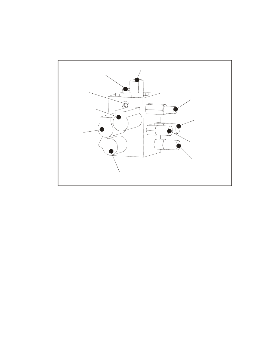
BRAKE
PRESSURE
SWITCH
MAIN RELIEF
STEER RELIEF
LIFT RELIEF
LIFT
FLOW
CONTROL
STEER
MP
HIGH PRESSURE
FILTER
Figure 4-18. Control Valve