Connection wico to station, Connection the device to pc – IKA HBC 10 control User Manual
Page 47
47
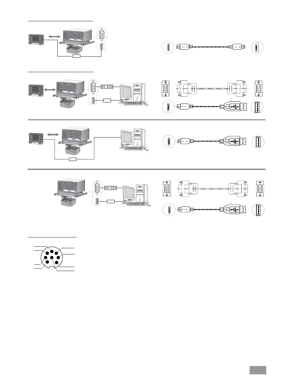
USB
USB Micro B
USB Micro A
Connection WiCo to Station:
Fig. 27
Micro B
Micro A
Connection the device to PC:
RS 232
USB
USB A
A
USB Micro B
USB A
9-pin RS 232
9-pin RS 232
or
USB
USB A
A
USB Micro B
USB A
RS 232
USB
USB A
or
A
9-pin RS 232
9-pin RS 232
USB Micro B
USB A
Fig. 28
Micro B
Micro B
Micro B
Multifunction interface:
1 M1 Output Valve + (+24Vdc/max. 0.8A)
2 M1 Output Valve - (max. 24Vdc/max. 0.8A)
3 M2 Output Alarm/Switch contact 1 (max. 30Vdc/ac/max. 1A)
4 M2 Output Alarm/Switch contact 2 (max. 30Vdc/ac/max. 1A)
5 M3 Input standby + (+5V ca. 10mA)
6 M3 Input standby - (0V only for Standby)
7 --- (reserved for later use, do not connect!)
8 --- (reserved for later use, do not connect!)
1
2
3
4
5
6
7
8
Fig. 29
This manual is related to the following products: