Advance adapters, inc, Atlas 2 speed rebuild kits – Advance Adapters AB1001 User Manual
Page 4
ADVANCE ADAPTERS, INC.
4320 Aerotech Center Way, Paso Robles, CA 93446
ASSEMBLY INSTRUCTION SHEET
Page 4 of 12 Rev. Date:
06-18-08
P/N AB1000 & AB1001
ATLAS 2 SPEED REBUILD KITS
Next, remove the shifter slider, the synchronizer springs, the synchronizer dogs and the brass rings.
Turn the case so that you are looking at the input ring. Remove the six bolts that hold it to the case. Use your dead
blow hammer to firmly hit the side of the transfer case while pulling on the input shaft. The tolerance on the input bore
should be a snug fit and may take a little while to work loose. We do not recommend using any type of prying mechanism
to get the input out; the aluminum is "softer" than a screwdriver or a pry bar and WILL get damaged and my cause
problems down the road. Once removed, there will be one synchro ring that will become free. Remove it from the
case, and place it in top of the synchro hub located on the input assembly you just removed.
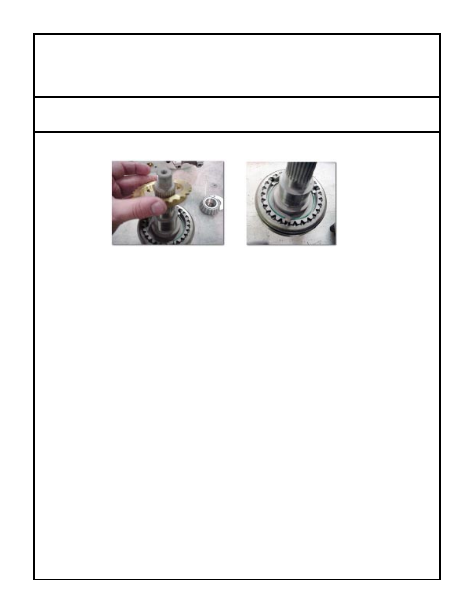
Using your fingers, "pop" the synchro slider off the slider hub. When removed, three synchro dogs will become loose.
They may simply "fall" out or even "spring" out.
Remove the speedometer drive from the tail housing. If you have no speedometer drive but do have a freeze plug
blocking the hole, disregard and go to the next step.
Using an 1-1/8" socket, remove the output shaft nut and discard it. Depending on the mileage of your unit, the rear
yoke may be difficult to remove. You can use a puller if it is stubborn but most yokes can be removed with the use
of a dead blow hammer. When the nut and yoke are off, the output shaft will become "loose" in the case. DO NOT
ATTEMPT TO REMOVE THE OUTPUT SHAFT FROM THE CASE YET! There are a couple of parts which
are still holding it into the case.
Remove the five bolts holding the tail housing on the case. You may need to tap the tail housing to get it loose from
the case. Take the housing completely off the case and set it aside.
Use a set of snap ring pliers to remove the first snap ring from the shaft. Next, remove the blue plastic drive gear from
the shaft (may be a slightly snug fit). Remove the last snap ring and set those parts aside.
The last thing holding the shaft into place is the bearing on it. This bearing is another "light" press, and will require the
use of the dead blow hammer. Use one hand to hit the tip of the shaft with the hammer and the other hand to support
the large "pancake" gear inside the case. Visualize that you are driving the output shaft through the pancake gear and
out the front of the case. When the bearing becomes loose, slide it completely off of the shaft. Place it into the "old"
parts section. Pull the shaft fully from the front of the case. There is one more brass synchro slider, and one caged
needle bearing set that are now free. Remove the pancake gear from the case. There should not be any more parts
loose inside the case. At this point it is wise to clean and inspect your case and parts for any debris. Also inspect the
outside of the case and remove any silicon or sealing material.
Place the pancake gear on a flat surface with the synchro hub facing up. Take one of the brass synchro rings and place