Operation manual, Magnetic switches – Class1 118253 - ITL40 108404-XX - Full User Manual
Page 8
FORM-ENG-0018 REV A 05-27-03
PAGE
7 of 25
S U I T A B L E F O R E X T E R N A L D I S T R I B U T I O N
OPERATION MANUAL
DATE
9/24/2008
PRODUCT GROUP
ITL40
P/N
118404-XX
REV
1.00
607 NW 27th Ave
Ocala, FL 34475
Ph: 352-629-5020 or 1-800-533-3569
Fax : 352-629-2902 or 1-800-520-3473
PRODUCT
Intelli-Tank Level 40
BY
AMS
MANUAL
P/N:118253
P
RINTED
:
1/8/09
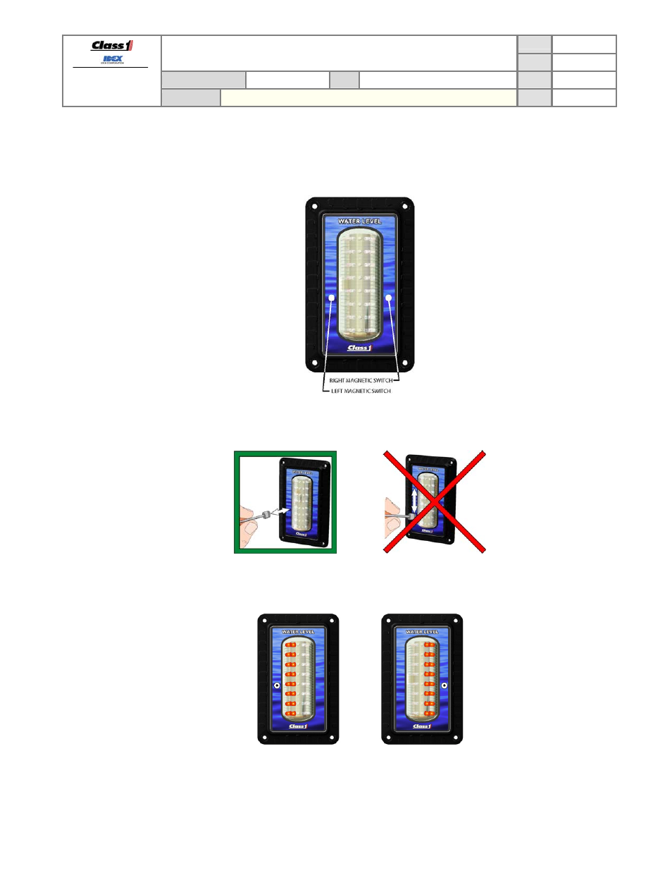
3.2. Magnetic
switches
The ITL40 has two magnetic switches (left and right). The switches are activated by touching a magnet to either side
of the display in the areas shown in picture below. The label has a small “o” to indicate the location of the magnetic
switch.
For best results the magnet should be positioned over the desired switch approximately 2 inches from the front of the
display, pushed directly to the front of the display, and then pulled back to the start position (do not using a swiping
motion).
The LEDs on the display will indicate which switch was activated for approximately half a second and then the display
will go blank (LEFT = left two columns of LEDs, RIGHT = right two columns of LEDs).
LEFT (L) indication RIGHT (R) indication
The maximum time between magnetic switch activations is two seconds. If longer than two seconds have passed
between activations the unit will resume normal operation and the password attempted will be cleared.