AEM Infinity Supported Applications - Universal V8 Engine User Manual
Page 44
44
© 2014 AEM Performance Electronics
Infinity
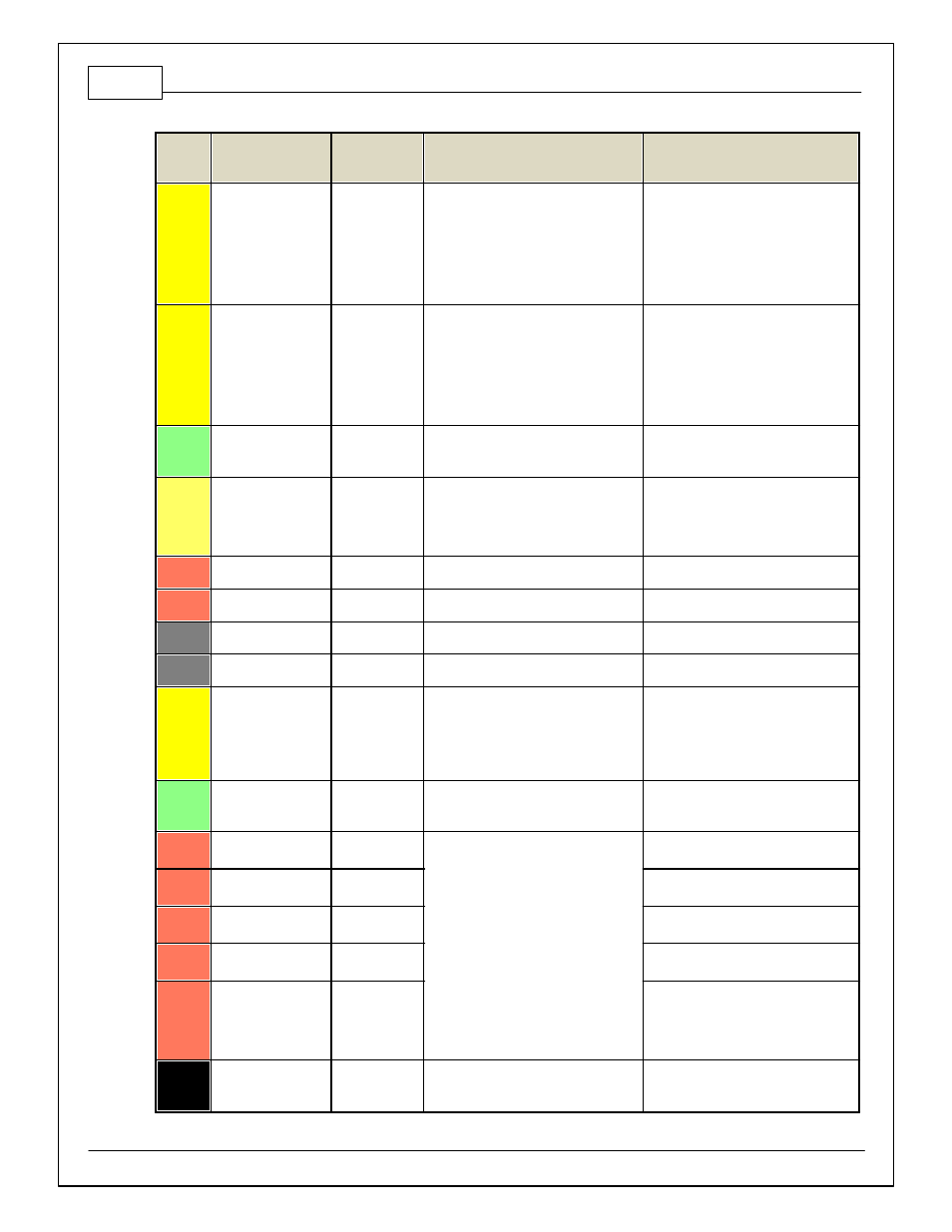
Pin
Hardware Ref.
7100-XXXX-62
7101-XXXX-63
Function
Hardware Specification
Notes
C2-35
Analog_In_22*
Spare Analog
Input
12 bit A/D, 100K pullup to 5V
0–5V analog signal. Use +5V Out pins as
power supply and Sensor Ground pins as
the low ref erence. Do not connect signals
ref erenced to +12V as this can
permanently damage the ECU. Normally
used as USB Logging Request input. *Pin
not populated in 30-3805 Univ ersal V8
Base harness.
C2-36
Analog_In_23*
Spare Analog
Input
12 bit A/D, 100K pullup to 5V
0–5V analog signal. Use +5V Out pins as
power supply and Sensor Ground pins as
the low ref erence. Do not connect signals
ref erenced to +12V as this can
permanently damage the ECU. Normally
used as Charge Out Pressure input. *Pin
not populated in 30-3805 Univ ersal V8
Base harness.
C2-37
Digital_In_6*
Spare Digital
Input
No pullup. Will work with TTL signals.
Input can be assigned to dif f erent pins.
See Setup Wizard page Input Function
Assignments f or input mapping options.
C2-38
Digital_In_7
Clutch Switch
No pullup. Will work with TTL signals.
See ClutchSwitch 1-axis table f or setup
options. Input can be assigned to
dif f erent pins. See Setup Wizard page
Input Function Assignments f or input
mapping options.
C2-39
Power Ground
Ground
Power Ground
Connect directly to battery ground.
C2-40
Power Ground
Ground
Power Ground
Connect directly to battery ground.
C2-41
CanH_Bout
CANH
Dedicated High Speed CAN Transceiv er
Not used
C2-42
CanL_Bout
CANL
Dedicated High Speed CAN Transceiv er
Not used
C2-43
LowsideSwitch_8
Engine Protect
Warning Out
Lowside switch, 4A max with internal
f ly back diode. Inductiv e load should NOT
hav e f ull time power.
Activ ates if any of the f ollowing f lags are
true: OilPressProtectOut,
LeanProtectOut, CoolantProtect. Output
can be assigned to other f unctions. See
Setup Wizard page LowSide Assignment
Tables f or additional options.
C2-44
LowsideSwitch_7*
LS7
Lowside switch, 4A max with internal
f ly back diode. Inductiv e load should NOT
hav e f ull time power.
Normally used as Spare GPO1 output.
*Pin not populated in 30-3805 Univ ersal
V8 Base harness.
C2-45
UEGO 2 VM
UEGO 2 VM
Bosch UEGO Controller
Virtual Ground signal. Connect to pin 5 of
Bosch UEGO sensor.
C2-46
UEGO 2 UN
UEGO 2 UN
Nernst Voltage signal. Connect to pin 1 of
Bosch UEGO sensor.
C2-47
UEGO 2 IP
UEGO 2 IP
Pumping Current signal. Connect to pin 6
of Bosch UEGO sensor.
C2-48
UEGO 2 IA
UEGO 2 IA
Trim Current signal. Connect to pin 2 of
Bosch UEGO sensor.
C2-49
UEGO 2 HEAT
UEGO 2 HEAT
Lowside switch f or UEGO heater control.
Connect to pin 4 of Bosch UEGO sensor.
NOTE that pin 3 of the Sensor is heater
(+) and must be power by a f used/
switched 12V supply .
C2-50
+12V_R8C_CPU
Battery Perm
Power
Dedicated power management CPU
Optional f ull time battery power. MUST be
powered bef ore the ignition switch input is
triggered. (See C1-65.)