AEM Infinity Supported Applications - Universal V8 Engine User Manual
Page 38
38
© 2014 AEM Performance Electronics
Infinity
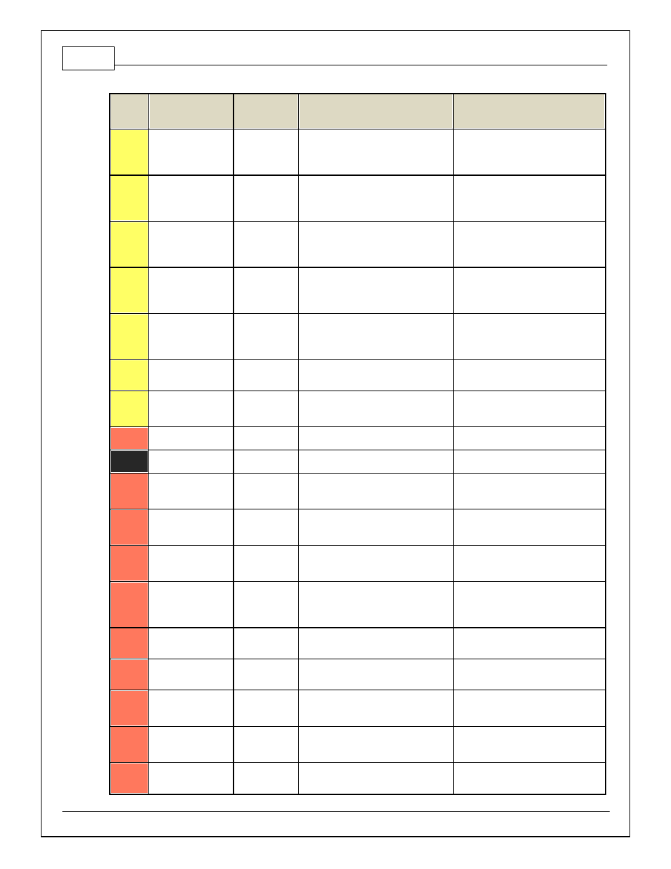
Pin
Hardware Ref.
7100-XXXX-62
7101-XXXX-63
Function
Hardware Specification
Notes
C1-12
Coil 3
Coil 3
25 mA max source current
0–5V Falling edge f ire. DO NOT connect
directly to coil primary . Must use an
ignitor OR CDI that accepts a FALLING
edge f ire signal.
C1-13
Coil 2
Coil 2
25 mA max source current
0–5V Falling edge f ire. DO NOT connect
directly to coil primary . Must use an
ignitor OR CDI that accepts a FALLING
edge f ire signal.
C1-14
Coil 1
Coil 1
25 mA max source current
0–5V Falling edge f ire. DO NOT connect
directly to coil primary . Must use an
ignitor OR CDI that accepts a FALLING
edge f ire signal.
C1-15
Coil 6
Coil 6
25 mA max source current
0–5V Falling edge f ire. DO NOT connect
directly to coil primary . Must use an
ignitor OR CDI that accepts a FALLING
edge f ire signal.
C1-16
Coil 5
Coil 5
25 mA max source current
0–5V Falling edge f ire. DO NOT connect
directly to coil primary . Must use an
ignitor OR CDI that accepts a FALLING
edge f ire signal.
C1-17
LowsideSwitch_2
Coolant Fan 1
Control
Lowside switch, 4A max, NO internal
f ly back diode.
See "LowSide Assignment Tables" f or
output assignment.
C1-18
LowsideSwitch_3
LS3
Lowside switch, 4A max with internal
f ly back diode. Inductiv e load should NOT
hav e f ull time power.
Normally used as MIL output. See Wizard
page "LowSide Assignment Tables" f or
output assignment.
C1-19
AGND_1
Sensor Ground
Dedicated analog ground
Analog 0–5V sensor ground
C1-20
AGND_1
Sensor Ground
Dedicated analog ground
Analog 0–5V sensor ground
C1-21
Crankshaf t Position
Sensor Hall
Crankshaf t
Position Sensor
Hall
10K pullup to 12V. Will work with ground
or f loating switches.
See Setup Wizard page Cam/Crank f or
options.
C1-22
Camshaf t Position
Sensor 1 Hall
Camshaf t
Position Sensor
1 Hall
10K pullup to 12V. Will work with ground
or f loating switches.
See Setup Wizard page Cam/Crank f or
options.
C1-23
Digital_In_2*
Camshaf t
Position Sensor
2 Hall
10K pullup to 12V. Will work with ground
or f loating switches.
See Setup Wizard page Cam/Crank f or
options. *Pin not populated in 30-3805
Univ ersal V8 Base harness.
C1-24
Digital_In_3*
Turbo Speed Hz
10K pullup to 12V. Will work with ground
or f loating switches.
See Setup Wizard page Input Function
Assignment f or calibration constant. *Pin
not populated in 30-3805 Univ ersal V8
Base harness.
C1-25
Digital_In_4
Vehicle Speed
Sensor
10K pullup to 12V. Will work with ground
or f loating switches.
See Setup Wizard page Input Function
Assignment f or calibration constant.
C1-26
Digital_In_5
Flex Fuel
10K pullup to 12V. Will work with ground
or f loating switches.
See channel FlexDigitalIn [Hz] f or raw
f requency input data.
C1-27
Knock Sensor 1*
Knock Sensor 1
Dedicated knock signal processor
See Setup Wizard page Knock Setup f or
options. *Pin not populated in 30-3805
Univ ersal V8 Base harness.
C1-28
Knock Sensor 2*
Knock Sensor 2
Dedicated knock signal processor
See Setup Wizard page Knock Setup f or
options. *Pin not populated in 30-3805
Univ ersal V8 Base harness.
C1-29
+12V_Relay _Control
+12V Relay
Control
0.7A max ground sink f or external relay
control
Will activ ate at key on and at key of f
according to the conf iguration settings.