AEM Infinity Supported Applications - Universal V8 Engine User Manual
Page 17
Universal 8
17
© 2014 AEM Performance Electronics
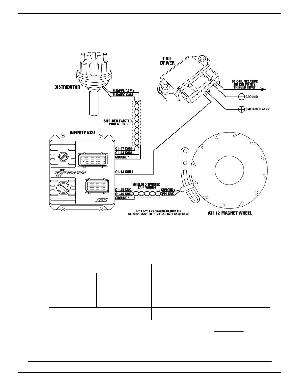
MSD Distributor + ATI Flying Magnet + MSD Non-Magnetic VR Sensor
1. Modify and install mechanical advance distributor. (See
Modifying Mechanical Advance Distributor
, in
this document.)
2. Install ATI Flying Magnet crank trigger. (Note that an adjustable sensor mount is not provided with the
ATI crank trigger.) Position the crank sensor to be near the middle of its adjustment range while being
in between magnet targets with the engine at TDC. Set sensor air gap to .040”.
3. Wiring – note that sensor wiring may be different from what MSD instructions indicate. The Infinity
ECU can only accept falling edge VR/mag wave forms. If in doubt, verify sensor signal with an
oscilloscope.
Crank Sensor – MSD Non-Magnetic VR Sensor
Cam Sensor – Modified MSD Distributor
Wire
Desc
Connect To
Wire
Desc
Connect To
Green Crank signal +
C1-45 Crk Pos Sens VR+
Black/
Purple
Cam signal + C1-48 Cam Pos Sens 1 VR+
Purple Crank signal -
C1-46 Crk Pos Sens VR-
Black/
Orange
Cam signal -
C1-47 Cam Pos Sens 1 VR-
Note: Use shielded tw isted pair w iring w /drain to
ground.
Note: Use shielded tw isted pair w iring w /drain to
ground.
4. Load ATI 12 + MSD Non-Mag base session and review Setup Wizard. (See
, in this
document.)
5. Sync ignition timing. (See
, in this document.)