AEM Infinity Supported Applications - Universal V8 Engine User Manual
Page 11
Universal 8
11
© 2014 AEM Performance Electronics
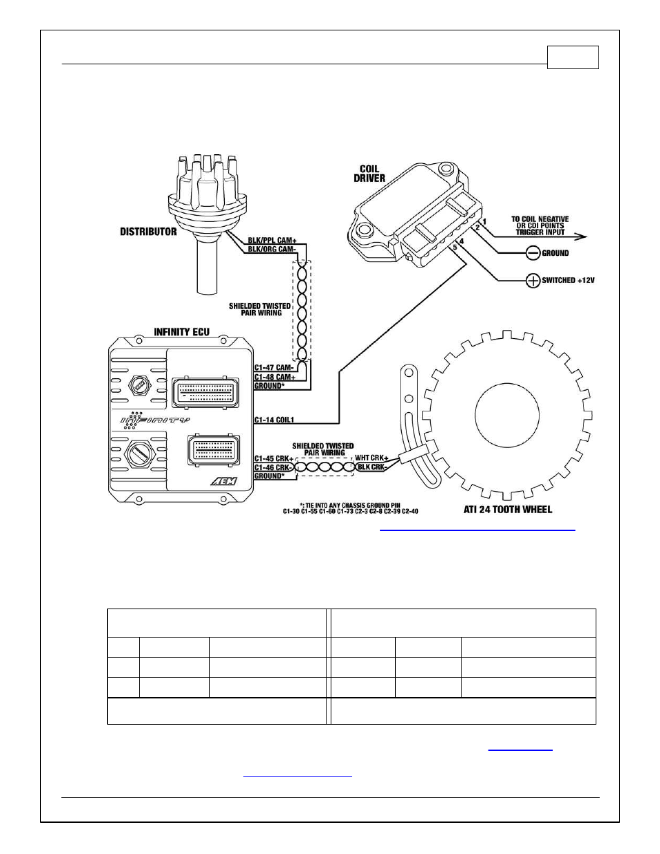
MSD Distributor + ATI AEM 24 Tooth + Honeywell High Output VR
Sensor
1. Modify and install mechanical advance distributor. (See
Modifying Mechanical Advance Distributor
, in
this document.)
2. Install ATI AEM Infinity crank trigger. (Note that an adjustable sensor mount is not provided with the
ATI crank trigger.) Position the crank sensor to be near the middle of its adjustment range while being
in between crank teeth with the engine at TDC. Set sensor output to .011”.
3. Wiring – note that the Infinity ECU can only accept falling edge VR/mag wave forms. If in doubt, verify
sensor signal with an oscilloscope.
Crank Sensor – Honeywell High Output VR
Sensor
Cam Sensor – Modified MSD Distributor
Wire
Desc
Connect To
Wire
Desc
Connect To
White Crank signal + C1-45 Crk Pos Sens VR+ Black/Purple
Cam signal + C1-48 Cam Pos Sens 1 VR+
Black Crank signal - C1-46 Crk Pos Sens VR-
Black/Orange Cam signal -
C1-47 Cam Pos Sens 1 VR-
Note: Use shielded tw isted pair w iring w /drain
to ground.
Note: Use shielded tw isted pair w iring w /drain to ground.
4. Load ATI 24 + Honeywell HO VR base session and review Setup Wizard. (See
, in this
document.)
5. Sync ignition timing. (See
, in this document.)