AEM Infinity Supported Applications - Honda 2001-2005 K-Series Engine User Manual
Page 8
8
© 2014 AEM Performance Electronics
Infinity
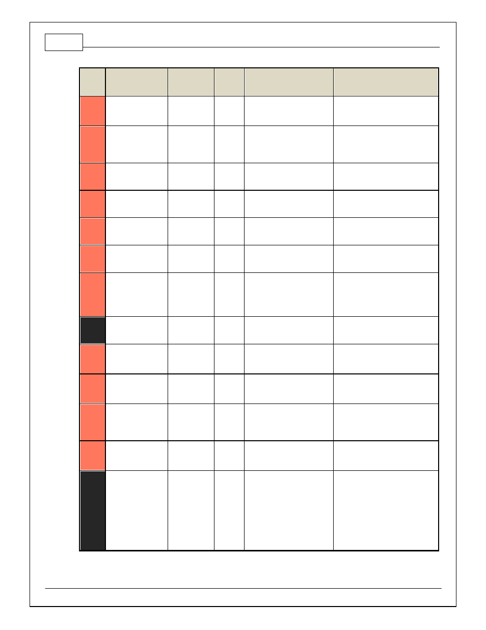
Pin
Hardware Reference
7100-XXXX-62
7101-XXXX-63
Function
Dest. Pin
Honda K
Hardware Specification
Notes
C1-23
Digital_In_2
Camshaf t
Position Sensor
2 Hall
A25
10K pullup to 12V. Will work with
ground or f loating switches.
See Setup Wizard page Cam/Crank f or
options.
C1-24
Digital_In_3
Turbo Speed Hz
10K pullup to 12V. Will work with
ground or f loating switches.
See Setup Wizard page Input Function
Assignment f or calibration constant.
TurboSpeed [RPM] = Turbo [Hz] * Turbo
Speed Calibration.
C1-25
Digital_In_4
Vehicle Speed
Sensor
A18
10K pullup to 12V. Will work with
ground or f loating switches.
See Setup Wizard page Input Function
Assignment f or calibration constant.
C1-26
Digital_In_5
Flex Fuel
10K pullup to 12V. Will work with
ground or f loating switches.
See channel FlexDigitalIn [Hz] f or raw
f requency input data.
C1-27
Knock Sensor 1
Knock Sensor 1
A9
Dedicated knock signal
processor
See Setup Wizard page Knock Setup
f or options.
C1-28
Knock Sensor 2
Knock Sensor 2
Dedicated knock signal
processor
See Setup Wizard page Knock Setup
f or options.
C1-29
+12V_Relay _Control
+12V Relay
Control
E7 &
Inf inity
Main
Relay
Trigger
0.7A max ground sink f or
external relay control
Will activ ate at key on and at key of f
according to the conf iguration settings.
C1-30
Power Ground
Ground
A5
Power Ground
Connect directly to battery ground.
C1-31
CANL_Aout
AEMNet CANL
Dedicated High Speed CAN
Transceiv er
Recommend twisted pair (one twist per
2") with terminating resistor. Contact
AEM f or additional inf ormation.
C1-32
CANH_Aout
AEMNet CANH
Dedicated High Speed CAN
Transceiv er
Recommend twisted pair (one twist per
2") with terminating resistor. Contact
AEM f or additional inf ormation.
C1-33
LowsideSwitch_1
Boost Control
Lowside switch, 4A max with
internal f ly back diode. Inductiv e
load should NOT hav e f ull time
power.
See Setup Wizard page Boost Control
f or options. Monitor BoostControl [%]
channel f or output state.
C1-34
Lowside Fuel Pump
driv e
Fuel Pump
E1
Lowside switch, 4A max, NO
internal f ly back diode.
Switched ground. Will prime f or 2
seconds at key on and activ ate if RPM
> 0.
C1-35
Analog_In_7
Throttle Position
Sensor
A15
12 bit A/D, 100K pullup to 5V
0–5V analog signal. Use +5V Out pins
as power supply and Sensor Ground
pins as the low ref erence. Do not
connect signals ref erenced to +12V as
this can permanently damage the ECU.
See the Setup Wizard Set Throttle
Range page f or automatic min/max
calibration. Monitor the Throttle [%]
channel. Also DB1_TPSA [%] f or DBW
applications.