Infinity supported application 15 – AEM Infinity Supported Applications - Honda 2001-2005 K-Series Engine User Manual
Page 15
Infinity Supported Application
15
© 2014 AEM Performance Electronics
Infinity
Pin
Hardware Reference
7100-XXXX-62
7101-XXXX-63
Function
Dest. Pin
Honda K
Hardware Specification
Notes
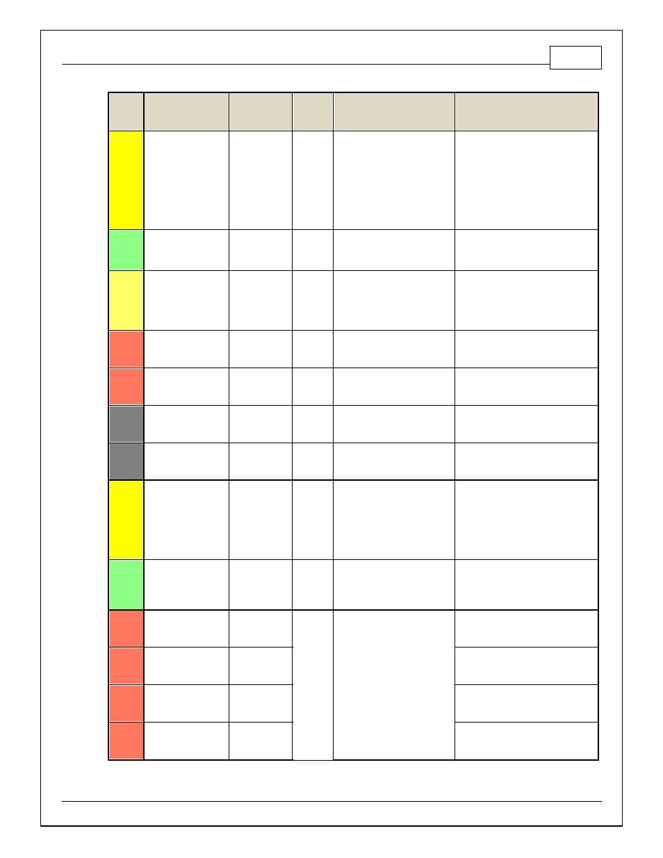
C2-36
Analog_In_23
Charge Out
Pressure
12 bit A/D, 100K pullup to 5V
0–5V analog signal. Use +5V Out pins
as power supply and Sensor Ground
pins as the low ref erence. Do not
connect signals ref erenced to +12V as
this can permanently damage the ECU.
See ChargeOutPress [kPa] channel f or
input state. See Setup Wizard page
Charge Out Pressure f or calibration
options.
C2-37
Digital_In_6
Spare Digital
Input
No pullup. Will work with TTL
signals.
Input can be assigned to dif f erent pins.
See Setup Wizard page Input Function
Assignments f or input mapping options.
C2-38
Digital_In_7
Clutch Switch
No pullup. Will work with TTL
signals.
See ClutchSwitch 1-axis table f or setup
options. Input can be assigned to
dif f erent pins. See Setup Wizard page
Input Function Assignments f or input
mapping options.
C2-39
Power Ground
Ground
Power Ground
Connect directly to battery ground.
C2-40
Power Ground
Ground
Power Ground
Connect directly to battery ground.
C2-41
CanH_Bout
CANH
Dedicated High Speed CAN
Transceiv er
Not used
C2-42
CanL_Bout
CANL
Dedicated High Speed CAN
Transceiv er
Not used
C2-43
LowsideSwitch_8
Engine Protect
Warning Out
B23
Lowside switch, 4A max with
internal f ly back diode. Inductiv e
load should NOT hav e f ull time
power.
Activ ates if any of the f ollowing f lags
are true: OilPressProtectOut,
LeanProtectOut, CoolantProtect.
Output can be assigned to other
f unctions. See Setup Wizard page
LowSide Assignment Tables f or
additional options.
C2-44
LowsideSwitch_7
Spare GPO1
Lowside switch, 4A max with
internal f ly back diode. Inductiv e
load should NOT hav e f ull time
power.
See Spare GPO1 Basic Setup section
of User GPIOs and PWM Setup Wizard
page LowSide Assignment Tables f or
additional options.
C2-45
UEGO 2 VM
UEGO 2 VM
Bosch UEGO Controller
Virtual Ground signal. Connect to pin 5
of Bosch UEGO sensor.
C2-46
UEGO 2 UN
UEGO 2 UN
Nernst Voltage signal. Connect to pin 1
of Bosch UEGO sensor.
C2-47
UEGO 2 IP
UEGO 2 IP
Pumping Current signal. Connect to pin
6 of Bosch UEGO sensor.
C2-48
UEGO 2 IA
UEGO 2 IA
Trim Current signal. Connect to pin 2 of
Bosch UEGO sensor.