Infinity supported application 19 – AEM Infinity Supported Applications - Dodge 2008-2010 Viper 4G User Manual
Page 19
Infinity Supported Application
19
© 2014 AEM Performance Electronics
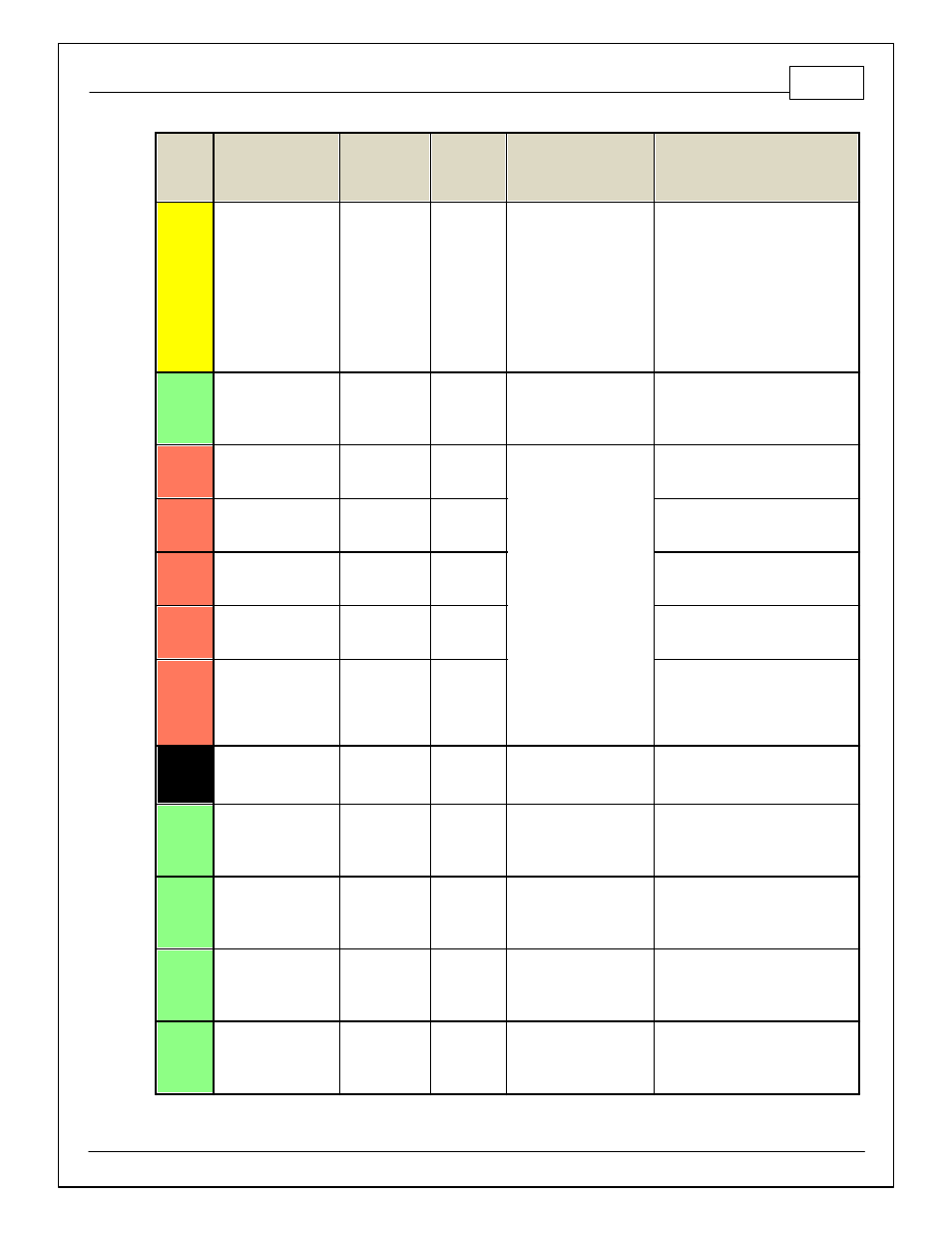
Infinity
Pin
Hardware Reference
08–10 Dodge
Viper Function
08–10
Dodge
Viper Pin
Destination
Hardware Specification
Notes
C2-43
LowsideSwitch_8
RAD Fan Relay
/ Control Engine
Protect Out
C4-3
Lowside switch, 4A max
with internal f ly back diode.
Inductiv e load should NOT
hav e f ull time power.
See Spare GPO1 Basic Setup section
of User GPIOs and PWM Setup Wizard
page LowSide Assignment Tables f or
additional options.
Activ ates if any of the f ollowing f lags
are true: OilPressProtectOut,
LeanProtectOut, CoolantProtect.
Output can be assigned to other
f unctions. See Setup Wizard page
LowSide Assignment Tables f or
additional options.
C2-44
LowsideSwitch_7
Rev erse Lock-
Out Control
C4-1
Lowside switch, 4A max
with internal f ly back diode.
Inductiv e load should NOT
hav e f ull time power.
See Spare GPO1 Basic Setup section
of User GPIOs and PWM Setup Wizard
page LowSide Assignment Tables f or
additional options.
C2-45
UEGO 2 VM
UEGO 2 VM
Bosch UEGO Controller
Virtual Ground signal. Connect to pin 5
of Bosch UEGO sensor.
C2-46
UEGO 2 UN
UEGO 2 UN
Nernst Voltage signal. Connect to pin 1
of Bosch UEGO sensor.
C2-47
UEGO 2 IP
UEGO 2 IP
Pumping Current signal. Connect to pin
6 of Bosch UEGO sensor.
C2-48
UEGO 2 IA
UEGO 2 IA
Trim Current signal. Connect to pin 2 of
Bosch UEGO sensor.
C2-49
UEGO 2 HEAT
UEGO 2 HEAT
Lowside switch f or UEGO heater
control. Connect to pin 4 of Bosch
UEGO sensor. NOTE that pin 3 of the
Sensor is heater (+) and must be power
by a f used/switched 12V supply .
C2-50
+12V_R8C_CPU
Battery Perm
Power
Dedicated power
management CPU
Optional f ull time battery power. MUST
be powered bef ore the ignition switch
input is triggered. (See C1-65.)
C2-51
Coil 7
Coil 7
C1-2
25 mA max source current
0–5V Falling edge f ire. DO NOT
connect directly to coil primary . Must
use an ignitor OR CDI that accepts a
FALLING edge f ire signal.
C2-52
Coil 8
Coil 8
C2-3
25 mA max source current
0–5V Falling edge f ire. DO NOT
connect directly to coil primary . Must
use an ignitor OR CDI that accepts a
FALLING edge f ire signal.
C2-53
Coil 9
Coil 9
C1-1
25 mA max source current
0–5V Falling edge f ire. DO NOT
connect directly to coil primary . Must
use an ignitor OR CDI that accepts a
FALLING edge f ire signal.
C2-54
Coil 10
Coil 10
C2-2
25 mA max source current
0–5V Falling edge f ire. DO NOT
connect directly to coil primary . Must
use an ignitor OR CDI that accepts a
FALLING edge f ire signal.