AEM Infinity Supported Applications - Dodge 2008-2010 Viper 4G User Manual
Page 12
12
© 2014 AEM Performance Electronics
Infinity
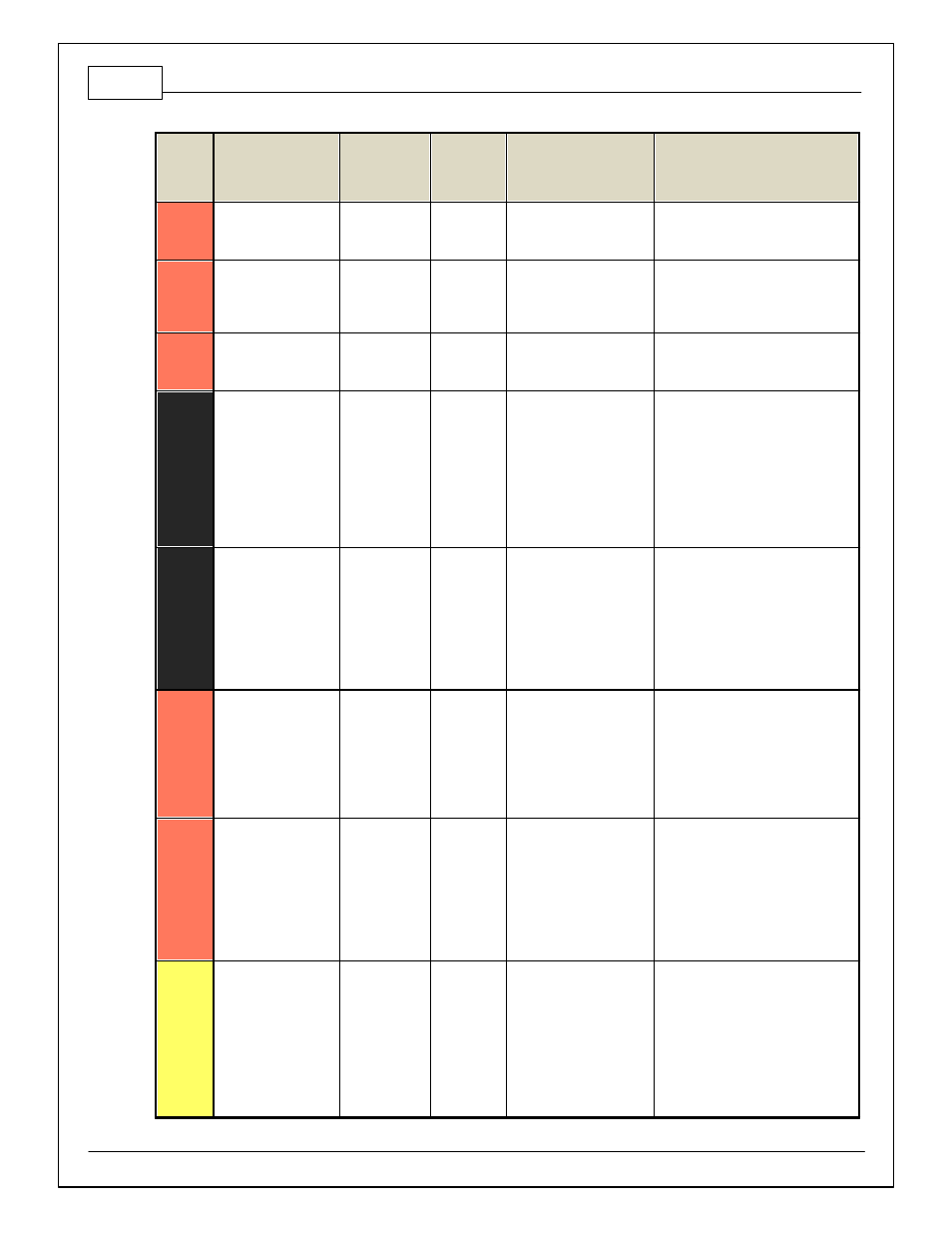
Pin
Hardware Reference
08–10 Dodge
Viper Function
08–10
Dodge
Viper Pin
Destination
Hardware Specification
Notes
C1-32
CANH_Aout
AEMNet CANH
Dedicated High Speed CAN
Transceiv er
Recommend twisted pair (one twist per
2") with terminating resistor. Contact
AEM f or additional inf ormation.
C1-33
LowsideSwitch_1
Boost Control
Lowside switch, 4A max
with internal f ly back diode.
Inductiv e load should NOT
hav e f ull time power.
See Setup Wizard page Boost Control
f or options. Monitor BoostControl [%]
channel f or output state.
C1-34
Lowside Fuel Pump
driv e
Fuel Pump
C4-4
Lowside switch, 4A max,
NO internal f ly back diode.
Switched ground. Will prime f or 2
seconds at key on and activ ate if RPM
> 0.
C1-35
Analog_In_7
Throttle Position
Sensor
C2-23
12 bit A/D, 100K pullup to
5V
0–5V analog signal. Use +5V Out pins
as power supply and Sensor Ground
pins as the low ref erence. Do not
connect signals ref erenced to +12V as
this can permanently damage the ECU.
See the Setup Wizard Set Throttle
Range page f or automatic min/max
calibration. Monitor the Throttle [%]
channel. Also DB1_TPSA [%] f or DBW
applications.
C1-36
Analog_In_8
MAP Sensor
C1-33
12 bit A/D, 100K pullup to
5V
0–5V analog signal. Use +5V Out pins
as power supply and Sensor Ground
pins as the low ref erence. Do not
connect signals ref erenced to +12V as
this can permanently damage the ECU.
See the Setup Wizard Set Manif old
Pressure page f or setup and
calibration. Monitor the MAP [kPa]
channel.
C1-37
Analog_In_9
Fuel Pressure
12 bit A/D, 100K pullup to
5V
0–5V analog signal. Use +5V Out pins
as power supply and Sensor Ground
pins as the low ref erence. Do not
connect signals ref erenced to +12V as
this can permanently damage the ECU.
See the Setup Wizard Fuel Pressure
page f or setup and calibration. Monitor
the FuelPressure [psig] channel.
C1-38
Analog_In_10
Baro Sensor
12 bit A/D, 100K pullup to
5V
0–5V analog signal. Use +5V Out pins
as power supply and Sensor Ground
pins as the low ref erence. Do not
connect signals ref erenced to +12V as
this can permanently damage the ECU.
See the Setup Wizard Barometric
Pressure page f or setup and
calibration. Monitor the BaroPress [kPa]
channel.
C1-39
Analog_In_11
Shif t Switch
Input
12 bit A/D, 100K pullup to
5V
0–5V analog signal. Use +5V Out pins
as power supply and Sensor Ground
pins as the low ref erence. Do not
connect signals ref erenced to +12V as
this can permanently damage the
ECU.
See the 1D lookup table 'Shif tSwitch'
f or setup. Also assignable to multiple
f unctions. See Setup Wizard f or
details.