AEM Infinity Supported Applications - Dodge 2008-2010 Viper 4G User Manual
Page 16
16
© 2014 AEM Performance Electronics
Infinity
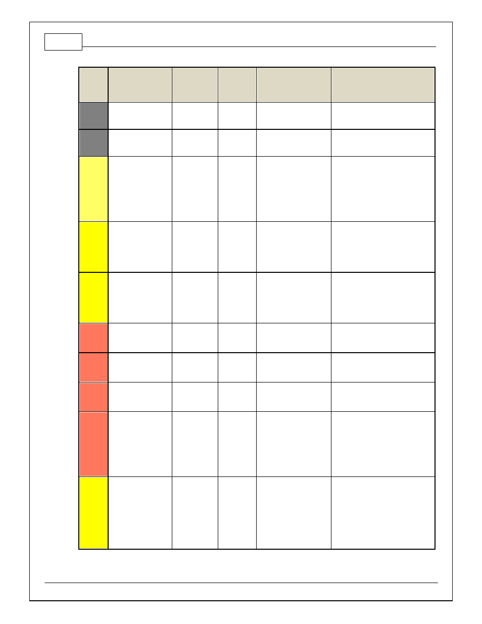
Pin
Hardware Reference
08–10 Dodge
Viper Function
08–10
Dodge
Viper Pin
Destination
Hardware Specification
Notes
C2-10
Injector 11
Injector 11
Saturated or peak and hold,
3A max continuous
Not used
C2-11
Injector 12
Injector 12
Saturated or peak and hold,
3A max continuous
Not used
C2-12
Analog_In_17
A/C Analog
Request
12 bit A/D, 100K pullup to
5V
0–5V analog signal. Use +5V Out pins
as power supply and Sensor Ground
pins as the low ref erence. Do not
connect signals ref erenced to +12V as
this can permanently damage the ECU.
See Setup Wizard Input Functions page
f or input selection. See AC_Request_In
1-axis table f or activ ation logic.
C2-13
Analog_In_18
DBW_APP1 [%]
C2-21
12 bit A/D, 100K pullup to
5V
0–5V analog signal. Use +5V Out pins
as power supply and Sensor Ground
pins as the low ref erence. Do not
connect signals ref erenced to +12V as
this can permanently damage the ECU.
C2-14
Analog_In_19
DBW_APP2 [%]
C1-32
12 bit A/D, 100K pullup to
5V
0–5V analog signal. Use +5V Out pins
as power supply and Sensor Ground
pins as the low ref erence. Do not
connect signals ref erenced to +12V as
this can permanently damage the ECU.
C2-15
Analog_In_Temp_4
Charge Out
Temperature
12 bit A/D, 2.49K pullup to
5V
See ChargeOutTemp [C] table f or
calibration data and ChargeOutTemp
[C] f or channel data.
C2-16
Analog_In_Temp_5
Airbox Temp /
Intake Air
Temperature
C1-16
12 bit A/D, 2.49K pullup to
5V
See AirboxTemp [C] table f or
calibration data and AirboxTemp [C] f or
channel data.
C2-17
Analog_In_Temp_6
Fuel
Temperature
12 bit A/D, 2.49K pullup to
5V
See FuelTemp [C] table f or calibration
data and FuelTemp [C] f or channel
data.
C2-18
Analog_In_13
Oil Pressure
C3-23
12 bit A/D, 100K pullup to
5V
0–5V analog signal. Use +5V Out pins
as power supply and Sensor Ground
pins as the low ref erence. Do not
connect signals ref erenced to +12V as
this can permanently damage the ECU.
See Setup Wizard Oil Pressure page f or
setup options. See OilPressure [psig]
f or channel data.
C2-19
Analog_In_14
Traction Control
Mode /
Sensitiv ity
12 bit A/D, 100K pullup to
5V
0–5V analog signal. Use +5V Out pins
as power supply and Sensor Ground
pins as the low ref erence. Do not
connect signals ref erenced to +12V as
this can permanently damage the ECU.
See the TC_SlipTrgtTrim [MPH] 1-axis
table. A multi-position rotary switch
such as AEM P/N 30-2056 is
recommended.