Page 4 of 21 – AEM 30-6053 Series 2 Plug & Play EMS User Manual
Page 4
Page 4 of 21
sensitive, you can depin Pin A1 that goes into the stock ECU, but the malfunction
code for this sensor will turn on. If this is done, the knock sensor calibration will need
to have 0.3 Volts added to each breakpoint in the calibration.
• Traction control function
When active, the stock traction control system will be affected by adding the EMS.
The stock traction control system uses throttle, fuel, and ignition changes for the
traction control system. Since the fuel and ignition are no longer controlled by the
stock ECU, these aspects of traction control must now be configured in the calibration
in the EMS. The throttle will still be cut as normal, but the traction and stability control
warning lights will stay on after the system is no longer activated and will reset when
the vehicle is turned off.
• EMS Fuel Map, Boost Fuel Trim Table
The 30-6053 calibration maps provided utilize the “Boost Fuel Trim Table” to provide
a 1:1 fuel compensation above atmospheric pressure. However, since the calibration
was created on a naturally aspirated vehicle (A calibration is provided above 100 kPa)
it has not been tested in boost and must be tuned to your application if turbo or
supercharged. To use this table, the “Boost Fuel Trim Table” should be configured to
provide twice as much fuel when the manifold pressure is twice as high and half the
fuel when the manifold pressure is half as high; this should help simplify the tuning
process for different vacuum and boost levels. Notice the values in the main “Fuel
Map”
do not change above 100 kPa (0 psi boost), the fuel correction is being made by
the “Boost Fuel Trim Table.”
Note: the “Boost Fuel Trim Table” must be adjusted if a different MAP sensor is
installed or if the Load breakpoints are adjusted. The Boost Fuel Trim value should be
set to -90 at 10kPa, 0 at 100 kPa, +100 at 200 kPa, +200 at 300 kPa, etc…
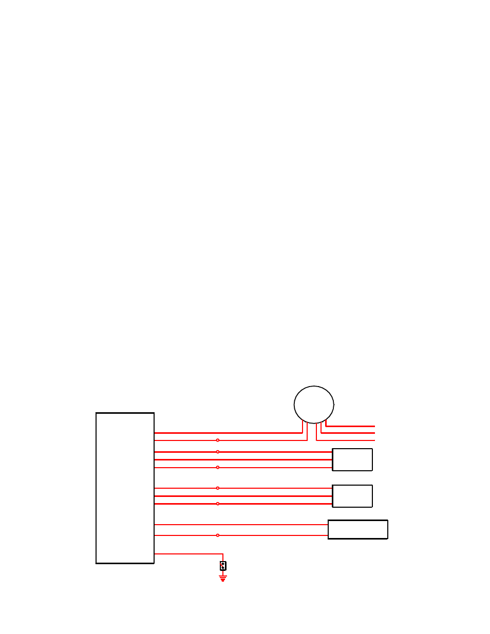
• Wiring accessories to the EMS
Please follow this suggested wiring diagram when adding new accessories and
retaining original accessories such as UEGO gauges, MAP sensors, MAF sensors,
IAT sensors, or switches for use with the EMS. Note that wire polarity is not important
for the Air Temperature sensor.
+5V Sensor Power (tapped)
Sensor Ground (tapped)
IAT Sensor
Sensor Ground (tapped)
MAP Signal
Sensor Ground (tapped)
O2 Sensor 1
Air Temperature Sensor
P/N: 30-2010
Black (Sensor Ground)
Green (MAP Signal)
Red (+5V Sensor Power)
Black (Battery or chassis ground)
Red (+12V power, 5A fuse)
AEM UEGO
P/N: 30-5130
Brown (Analog - signal)
White (0-5V Analog + signal)
Pink (Switched +12V Power)
MAP Sensor
P/N: 30-2130-50
+5V Sensor Power (tapped)
MAF Signal
Sensor Ground (tapped)
MAF Signal
Black (Sensor Ground)
Red (+5V Sensor Power)
MAF Sensor
AEM EMS
P/N: 30-6053
C16
A7, A31, C7, C18, or D9
Switch 1
Switched Input
Ground
A7, A31, C7, C18, or D9
A7, A31, C7, C18, or D9
A7, A31, C7, C18, or D9
C19 or C28
C17
C19 or C28
A29
C25
A31