Wire view of aem ems – AEM 30-6053 Series 2 Plug & Play EMS User Manual
Page 19
Page 19 of 21
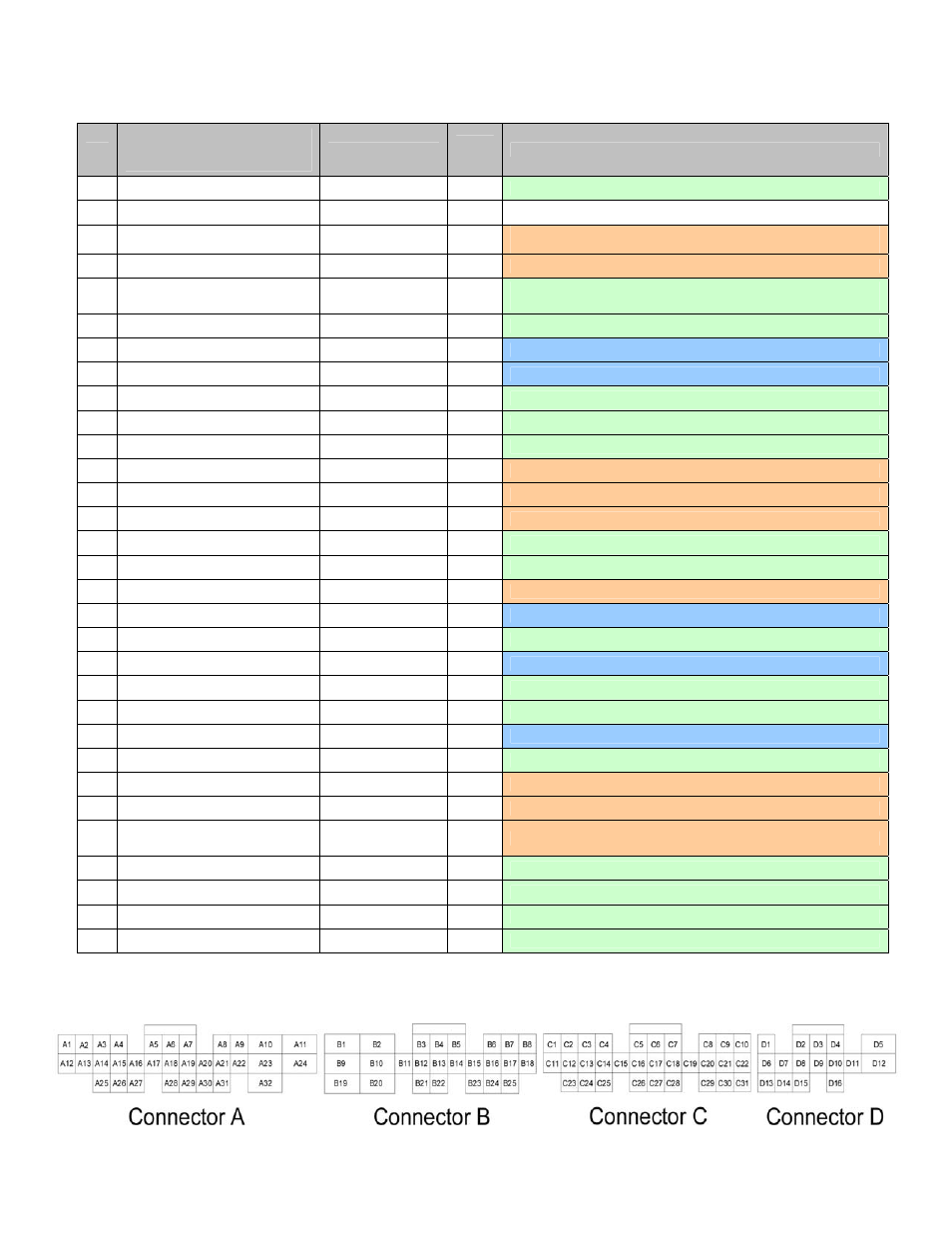
Connection Diagram for EMS P/N 30-6053
Pin
AEM adapter harness pinout
(gray connectors wired to
vehicle wiring harness)
AEM EMS 30-6053
EMS
I/O
EMS pin description
C1
--
Low side 2
Output
Available, switched ground, 1.5A max
C2
-- --
--
Not
used
C3
Knock sensor
Knock 1
Input
PnP for knock sensor signal
(depin from stock ECU if more sensitivity is required)
C4
Ignition coil 1
Coil 1
Output
PnP for ignition coil 1 (connected to B13)
C5
-- EGT
4
Input
Available, exhaust gas temperature sensor number 4,
jumper set for 0-5V input
C6
-- ADCR11
Input
Available, 0-5V sensor signal
C7
Sensor ground 1
Sensor ground
Output
Dedicated, filtered ground for sensors
C8
Crankshaft position sensor
Crank sensor (T1)
Input
Dedicated, crank position sensor signal
C9
-- Timing
ground
Output
Available, filtered ground for speed sensors (T1-T4)
C10
-- Switch
4
Input
Available, switched ground input signal number 4
C11
-- Injector
10
Output
Available, pulse width modulated switched ground, 1.5A max
C12
Ignition coil 2
Coil 2
Output
PnP for ignition coil 2
C13
Ignition coil 3
Coil 3
Output
PnP for ignition coil 3
C14
Ignition coil 4
Coil 4
Output
PnP for ignition coil 4
C15
-- O2
#2
Input
Available, 0-5V air-fuel ratio sensor number 2 signal
C16
-- O2
#1
Input
Available, 0-5V air-fuel ratio sensor number 1 signal
C17
MAP signal
MAP
Input
PnP for manifold absolute pressure sensor signal
C18
Sensor ground 2
Sensor ground
Output
Dedicated, filtered ground for sensors
C19
--
+5V sensor power
Output
Available, +5V sensor power
C20
Camshaft position sensor
Cam sensor (T2)
Input
Dedicated, cam position sensor signal
C21
-- Timing
ground
Output
Available, filtered ground for speed sensors (T1-T4)
C22
-- Knock
2
Input
Available, 0-5V knock sensor signal (connected to B24)
C23
Vehicle speed sensor
Vehicle speed (T3)
Input
Dedicated, vehicle speed sensor signal (connected to A9)
C24
-- ADCR13
Input
Available, 0-5V sensor signal, 100kΩ pull up resistor to 5V
C25
Intake air temperature sensor
AIT
Input
PnP for intake air temperature sensor signal
C26
Coolant temperature sensor
Coolant
Input
PnP for coolant temperature sensor signal
C27
Throttle position sensor (located
in wiring harness, not stock ECU)
TPS Input
PnP for throttle position sensor signal
C28
--
+5V sensor power
Output
Available, +5V sensor power
C29
-- Spare
speed
(T4)
Input Available, 0-5V speed sensor signal
C30
-- Timing
ground
Output
Available, filtered ground for speed sensors (T1-T4)
C31
-- Timing
ground
Output
Available, filtered ground for speed sensors (T1-T4)
Wire View of AEM EMS