Wire view of aem ems, F22c1 – AEM 30-6053 Series 2 Plug & Play EMS User Manual
Page 15
Page 15 of 21
Application Notes for EMS P/N 30-6053
F22C1
Make: Acura/Honda
Description Function
Pin
Model:
S2000
Spare Injector Drivers:
Injector 5
D1
Years Covered:
2006-2008
Spare Injector Drivers:
Injector 6
B19
Engine Displacement:
2.2L
Spare Injector Drivers:
Injector 7
D2
Engine Configuration:
Inline 4
Spare Injector Drivers:
Injector 8
B16
Firing Order:
1-3-4-2
Spare Injector Drivers:
Injector 9
A12 or A13
N/A, S/C or T/C:
N/A
Spare Injector Drivers:
Injector 10
C11
Load Sensor Type:
MAP
Spare Injector Drivers:
Injector 11
A14
MAP Min:
0.32V @ -13.9 psi
Spare Injector Drivers:
Injector 12
A10
MAP Max:
4.84V @ 10.94 psi
Spare Coil Drivers:
Coil 7
A13*
# Coils:
4 smart coils with built in ignitors
Spare Coil Drivers:
Coil 8
A22*
Ignition driver type:
0-5V Falling Edge trigger
Boost Solenoid:
PW 2
D16
# of Injectors:
4 (Inj 1-4)
Spare PWM Freq Driver:
PW 1
B15 or B23
Factory Injectors:
360 cc/min saturated
EGT 1 Location:
EGT 1
A5
Factory Inj Resistors:
No
EGT 2 Location:
EGT 2
D7
Injection Mode:
Sequential
EGT 3 Location:
EGT 3
A30
Knock Sensors used:
1 (Knock 1)
EGT 4 Location:
EGT 4
C5
Lambda Sensors used:
Spare 0-5V Input Channel:
ADCR03
A29
Spare 0-5V Input Channel:
ADCR11
C6
1 (O2 # 1, wideband sensor required,
original O2 sensor used only for
original check engine light)
Spare 0-5V Input Channel:
ADCR13
C24
Idle Control:
Stock electronic throttle
Spare 0-5V Input Channel:
ADCR14
D8
Main Relay Control:
Controlled by stock ECU
Spare Low Side Output Driver:
Low side 1
A2
Crank Pickup Type:
Hall Effect (3-wire)
Spare Low Side Output Driver:
Low side 2
C1
Crank Teeth/Cycle:
24 plus 2
Spare Low Side Output Driver:
Low side 4
A6
Cam Pickup Type:
Hall Effect (3-wire)
Spare Low Side Output Driver:
Low side 5
A4
Cam Teeth/Cycle:
4 plus 1
Spare Low Side Output Driver:
Low side 7
A19
Transmissions Offered:
Manual
Spare Low Side Output Driver:
Low side 10
A18
Trans Supported:
Manual
Spare Low Side Output Driver:
Low side 12
A8
Drive Options:
RWD
Spare Low Side Output Driver:
Idle 2
A28
Supplied Connectors:
N/A
Spare Low Side Output Driver:
Idle 4
D5
AEM Extension/patch harness
30-2986C (from vehicle harness)
Spare Low Side Output Driver:
Idle 6
B17
AEM Plug/pin kit
35-2610
Spare Low Side Output Driver:
Idle 8
B25
VTEC High Side Driver:
High side 1
B12
Spare High Side Driver:
High side 2
B7
Spare High Side Driver:
Idle 1
D3
Spare High Side Driver:
Idle 3
A25
Spare High Side Driver:
Idle 5
B8
Spare High Side Driver:
Idle 7
B18
Spare Switch Input:
Switch 1
A32
Spare Switch Input:
Switch 2
D11
Spare Switch Input:
Switch 3
D12
Spare Switch Input:
Switch 5
C10
A/C Switch Input:
Switch 6
A27
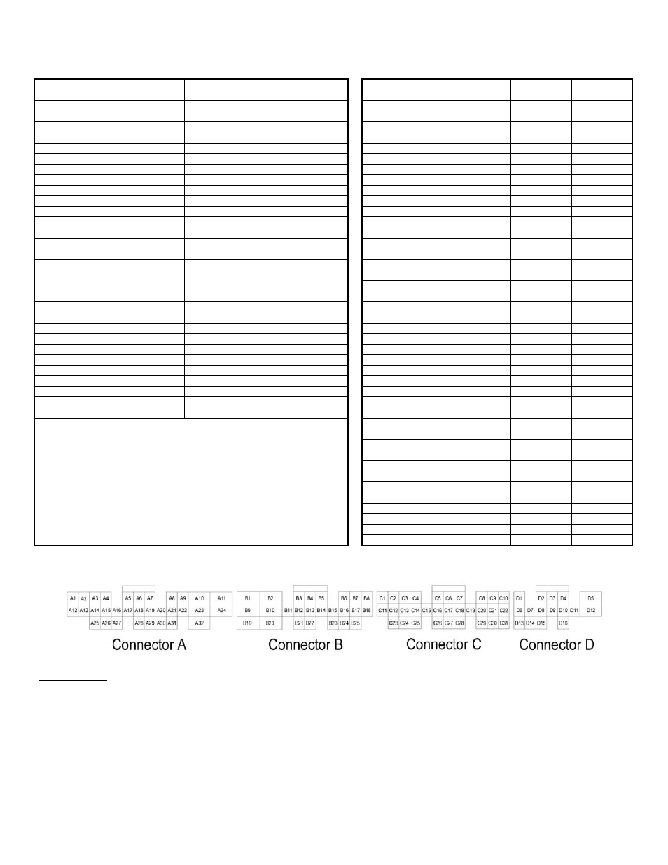
Wire View of AEM EMS
WARNING:
*The Coil 7 and Coil 8 outputs are intended only for use with ignitors (or smart coils with built-in
ignitors). Do not connect these pins directly to 2-wire direct-fire ignition coils (a.k.a. ‘dumb’ coils);
doing so will damage your EMS and void your warranty.
All switch input pins must connect to ground, the switch should not provide 12V power to the EMS
because that will not be detected as on or off. Connecting 12V power to the switch input pins may
damage your EMS and void your warranty.