Relay pinout, Wire view of aem ems, Wire view of relay – AEM 30-6053 Series 2 Plug & Play EMS User Manual
Page 20
Page 20 of 21
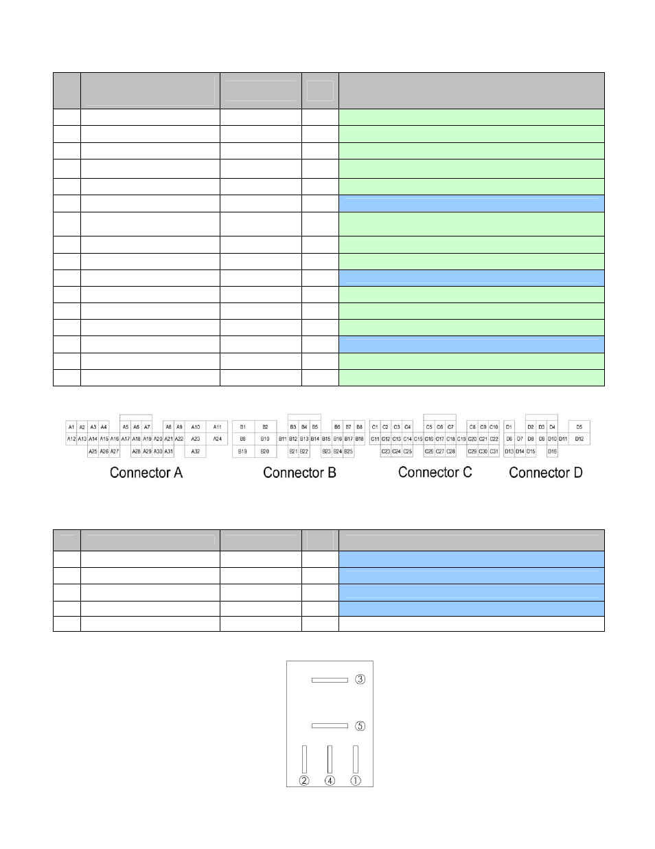
Connection Diagram for EMS P/N 30-6053
Pin
AEM adapter harness pinout
(gray connectors wired to
vehicle wiring harness)
AEM EMS 30-
6053
EMS
I/O
EMS pin description
D1
-- Injector
5
Output
Available, pulse width modulated switched ground, 1.5A max
D2
-- Injector
7
Output
Available, pulse width modulated switched ground, 1.5A max
D3
-- Idle
1
Output
Available, switched ground, 1.5A max
D4
--
High side 4
Output
Available, switched +12V power
D5
-- Idle
4
Output
Available, switched +12V power, 1.5A max
D6
Relay pin 3
+5V filtered power
Input
Dedicated, EMS shut off
D7
-- EGT
2
Input
Available, exhaust gas temperature sensor number 2, jumper set
for 0-5V input
D8
-- ADCR14
Input
Available, 0-5V sensor signal, 100kΩ pull up resistor to 5V
D9
-- Sensor
ground
Output
Available, filtered ground for sensors
D10
-- CAN1H
--
Dedicated, CAN1 high side
D11
-- Switch
2
Input
Available, switched ground input signal number 2
D12
-- Switch
3
Input
Available, switched ground input signal number 3
D13
--
High side 3
Output
Available, switched +12V power, 1.5A max
D14
-- CAN1L
--
Dedicated, CAN1 low side
D15
-- Baro
volts
Input
Available, barometric pressure sensor signal
D16
-- PW
2
Output
Available, boost solenoid pulse-width modulated switched ground
Wire View of AEM EMS
Relay pinout
Pin
Relay pinout
Destination
Relay
I/O
Relay pin description
1
+12V switched input
Stock ECU E9
Input
Dedicated
2
Ground
Stock ECU A5
Input
Dedicated
3
Ground to +5V line
AEM EMS D6
Output
Dedicated, used to power AEM EMS off properly
4
Ground
Stock ECU A5
Input
Dedicated
5
-- --
-- Not
used
Wire view of relay