Wire view of aem ems – AEM 30-6053 Series 2 Plug & Play EMS User Manual
Page 17
Page 17 of 21
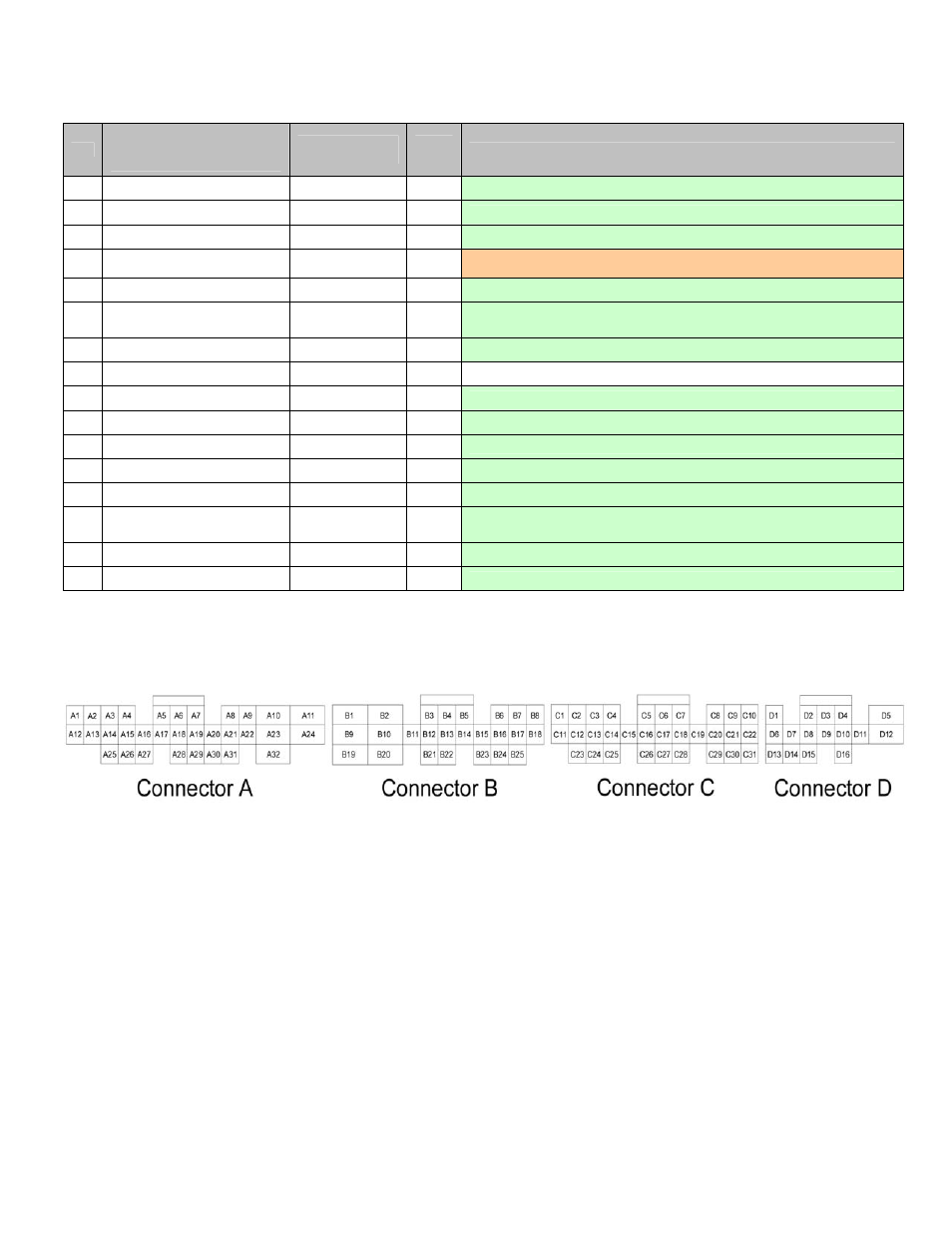
Connection Diagram for EMS P/N 30-6053
Pin
AEM adapter harness pinout
(gray connectors wired to
vehicle wiring harness)
AEM EMS 30-
6053
EMS
I/O
EMS pin description
A17
--
Low side 6
Output
Available, switched ground, 1.5A max
A18
--
Low side 10
Output
Available, switched ground, 1.5A max
A19
--
Low side 7
Output
Available, switched ground, 1.5A max
A20
Radiator fan control
Low side 8
Output
PnP for radiator fan control (cannot be set higher than stock ECU
temperature of 95°F/35°C unless tapped wire at stock ECU is disconnected)
A21
-- +12V
power
Output
Available, filtered +12V power
A22
--
Coil 8
Output
Available, 0-5V falling edge signal
(only available for use with 3-wire smart coils)
A23
--
O2 #2
Input
Available, 0-5V air-fuel ratio sensor number 2 signal
A24
--
+12V start signal
Input
Not used
A25
--
Idle 3
Output
Available, switched ground, 1.5A max
A26
-- Switch
5
Input
Available, switched ground input signal number 5
A27
--
Switch 6
Input
Available, switched ground input signal number 5
A28
--
Idle 2
Output
Available, switched +12V power, 1.5A max
A29
--
MAF
Input
Available, 0-5V mass air flow sensor signal
A30
--
EGT 3
Input
Available, exhaust gas temperature sensor number 3,
jumper set for 0-5V input
A31
--
Sensor ground
Output
Available, filtered ground for sensors
A32
--
Switch 1
Input
Available, switched ground input signal number 1
Wire View of AEM EMS