Wire view of aem ems – AEM 30-6053 Series 2 Plug & Play EMS User Manual
Page 18
Page 18 of 21
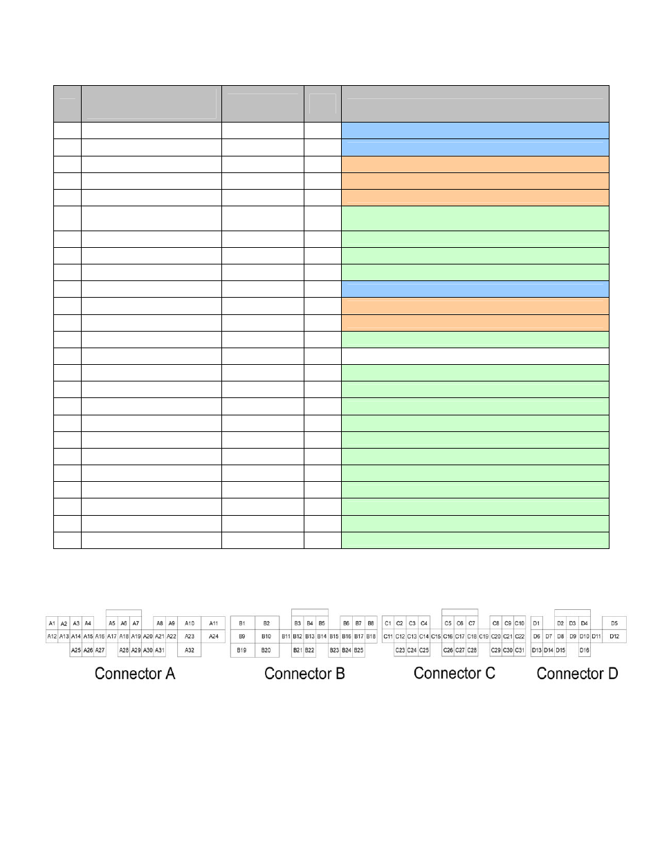
Connection Diagram for EMS P/N 30-6053
Pin
AEM adapter harness pinout
(gray connectors wired to
vehicle wiring harness)
AEM EMS 30-
6053
EMS
I/O
EMS pin description
B1
Ignition signal
+12V switched
Input
Dedicated, +12V power for AEM EMS
B2
Power ground 1
Power ground
Input
Dedicated, power ground for AEM EMS
B3
Injector 2
Injector 2
Output
PnP for injector number 2
B4
Injector 3
Injector 3
Output
PnP for injector number 3
B5
Injector 4
Injector 4
Output
PnP for injector number 4
B6
-- PW
1i
Output
Available, pulse width modulated switched ground, 1.5A max
(inverted signal to PW 1)
B7
--
High side 2
Output
Available, switched +12V power, 1.5A max
B8
-- Idle
5
Output
Available, switched ground, 1.5A max
B9
-- +12V
switched
Output
Available, switched +12V power (powered on when B1 is on)
B10
Power ground 2
Power ground
Input
Dedicated, power ground for AEM EMS
B11
Injector 1
Injector 1
Output
PnP for injector number 1
B12
VTEC solenoid valve
High side 1
Output
PnP for VTEC engagement signal
B13
-- Coil
1
Output
Available, 0-5V falling edge signal number 1 (connected to C4)
B14
-- --
-- Not
used
B15
-- PW
1
Output
Available, pulse width modulated switched ground, 1.5A max
B16
-- Injector
8
Output
Available, pulse width modulated switched ground, 1.5A max
B17
-- Idle
6
Output
Available, switched +12V power, 1.5A max
B18
-- Idle
7
Output
Available, switched ground, 1.5A max
B19
-- Injector
6
Output
Available, pulse width modulated switched ground, 1.5A max
B20
-- Power
ground
Output
Available, power ground
B21
-- +12V
switched
Input
Available, switched +12V power
B22
-- Power
ground
Output
Available, power ground
B23
-- PW
1
Output
Available, pulse width modulated switched ground, 1.5A max
B24
-- Knock
2
Input
Available, 0-5V knock sensor signal (connected to C22)
B25
-- Idle
8
Output
Available, switched +12V power, 1.5A max
Wire View of AEM EMS