Figure 6-4: installing locking valve stem, Figure 6-5: locking cam view, Figure 6-6: installing the valve ball – Hale Torrent SVS Stainless Steel Valves User Manual
Page 32: See figure 6-4: “installing
❑ Corrective Maintenance
32
Torrent SVS Installation / Operation Manual
p/n: 029-0020-90-0
❑
Install the valve STOP.
Lightly coat the valve
STOP stud thread with
Loctite #242 or equiva-
lent, then install the
valve STOP 1/4” nut.
❑
Using a criss-cross pat-
tern, tighten and torque
the three 1/4”-20 screws
and valve STOP nut to
20 ft.-lbs. (27 N-m).
❑
Tighten and torque the
handle hex screw (1/4”-
20) to 10 in.-lbs.
(14 N-m).
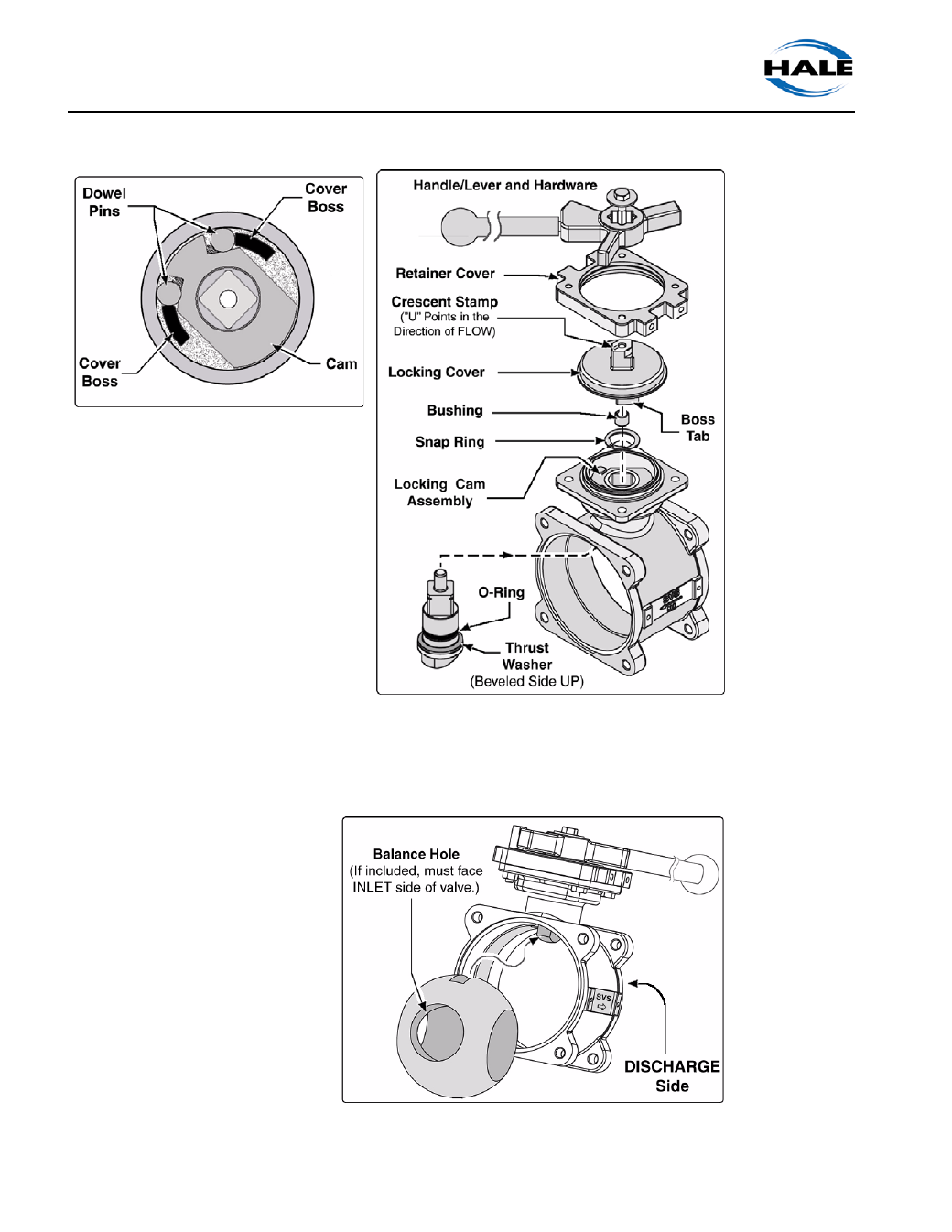
7.
Install the valve ball by
carefully sliding it into
the valve body opening
(from either side).
(See Figure 6-6:
“Installing the Valve
Ball.”)
If the valve ball
includes a balance
hole, the balance hole
must face the INLET
side of the valve.
Figure 6-4: Installing Locking Valve Stem
Figure 6-5: Locking Cam View
Figure 6-6: Installing the Valve Ball