Slow-close” valve handle, Figure 3-3: slow-close actuator assembly, 3 using adjustable linkage – Hale Torrent SVS Stainless Steel Valves User Manual
Page 18: Using adjustable linkage
❑ Installation
18
Torrent SVS Installation / Service Manual
p/n: 029-0020-90-0
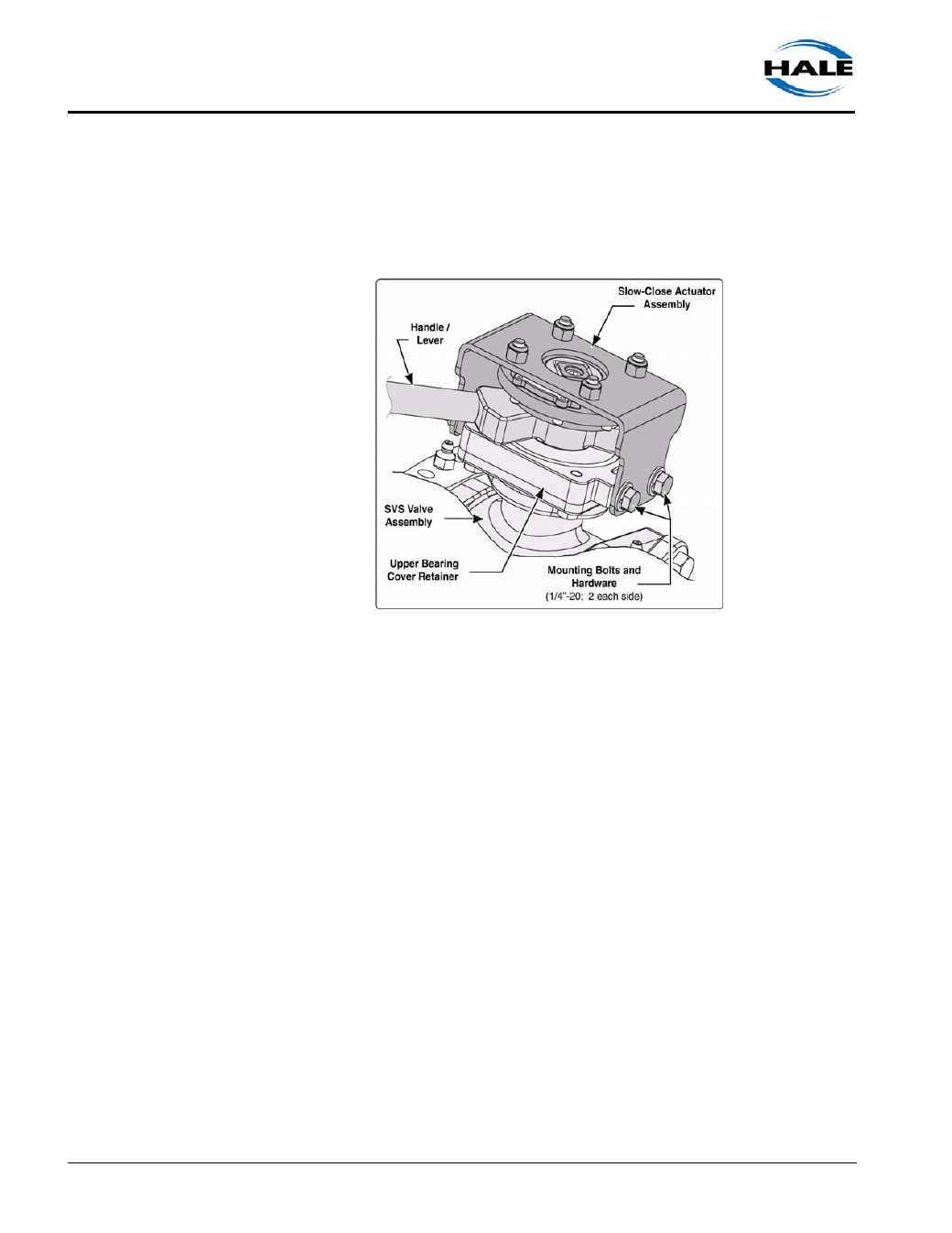
“Slow-Close” Valve Handle
If your valve includes the slow-close actuator, to remove and reposition the han-
dle proceed as follows:
1.
Remove the four (4) 1/4”-20
screws and hardware secur-
ing the slow-close actuator
assembly to the SVS valve
bearing cover. (See Figure
3-3: “Slow-Close Actuator
Assembly.”)
2.
Lift the slow-close assembly
from the valve stem.
3.
To remove and reposition
the handle, see heading
“Manual “Non-Locking or
Locking” Valve Handle” on
page 17.
4.
Depending on the original
orientation, rotate the valve
stem 90° (using appropriate wrench).
Note: If switching from left-hand-to-close to right-hand-to-close, rotate the valve stem
in the clockwise direction. If switching from right-hand-to-close to left-hand-to-close,
rotate in the counterclockwise direction.
5.
Install the slow-close assembly to the SVS valve bearing cover. (See Figure
3-3: “Slow-Close Actuator Assembly.”)
Apply Loctite #242 and install the four (4) 1/4”-20 screws.
6.
Using a criss-cross pattern, tighten and torque the three 1/4”-20 screws and
valve STOP nut to 20 ft.-lbs. (27 N-m).
7.
Open and close the valve a few times checking for smooth operation with
“resistance.”
3.3
USING ADJUSTABLE LINKAGE
For Hale recommended installation and minimum and maximum angle require-
ments when valve linkage is used, see Plate Drawing # PL1067A, located at the
back of this manual.
Figure 3-3: Slow-Close Actuator Assembly