Floppy interface connector (j14), Eide hard disk interface, Floppy interface connector (j14) –26 – Ampro Corporation LITTLE BOARD 5001451A User Manual
Page 44: Eide hard disk interface –26
2-26
If you don’t use the floppy interface, disable it in Setup. This frees the floppy’s I/O addresses, IRQ6,
and DMA channel 2 for use by other peripherals installed on the PC/104 bus.
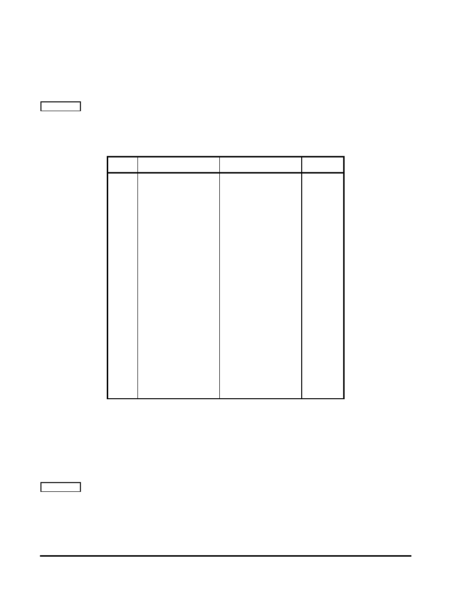
Floppy Interface Connector (J14)
Table 2-25 shows the pinout and signal definitions of the floppy disk interface connector, J14. This
pinout does not meet the AT standard for floppy drive cables. An adapter board can be purchased
from Ampro that will interface the 26-pin 2mm connector to a standard 3.5” floppy disk connector.
Table 2-25. Floppy Disk Interface Connector (J14)
Pin #
Signal Name
Function
In/Out
1
2
4
6
8
10
11
12
14
15
16
18
20
22
24
26
-
KEY
DEN
IDX*
MO1*
DS2*
DS1*
MO2*
DIRC*
STEP*
WD*
WE*
TRKO*
WP*
RDD*
HS*
DCHG*
Other Odd Pins
Cable Key Pin
Speed/Precomp
Index Pulse
Motor On 1
Drive Select 2
Drive Select 1
Motor On 2
Direction Select
Step
Write Data
Write Enable
Track 0
Write Protect
Read Data
Head Select
Disk Change
Signal grounds
N/A
OUT
IN
OUT
OUT
OUT
OUT
OUT
OUT
OUT
OUT
IN
IN
IN
OUT
IN
N/A
EIDE Hard Disk Interface
The Little Board P6d system provides an interface for up to four Integrated Device Electronics
(IDE) peripheral devices, such as hard disk drives and CD-ROM drives.
The primary IDE interface appears at connector J6, a 44-pin 2mm, dual-row connector.
The secondary IDE interface appears at connector J7, also a 44-pin 2mm, dual-row connector.
Table 2-26 shows the interface signals and pin outs for the IDE interface connectors. Both pinouts
are identical.