Connector summary, Connector summary –3 – Ampro Corporation LITTLE BOARD 5001451A User Manual
Page 21
Little Board P6d Module
2-3
Connector Summary
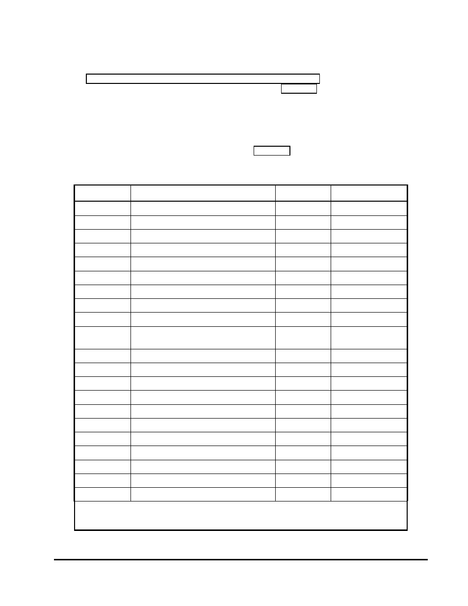
Refer to Figure 2-2. Little Board P6d Connector and Jumper Locations for the locations of the
connectors (J1 – J21) and configuration jumpers (W1 – W9). Table 2-1 summarizes the use of the
I/O connectors.
Each interface is described in its own section, showing connector pinouts, signal definitions,
required mating connectors, and configuration jumper options.
Many of the connectors have a key pin removed. This allows you to block the corresponding cable
connector socket to help prevent improper assembly. Table 2-1 indicates which pins are key pins.
Table 2-1. Connector Summary
Connector
Function
Size
Key Pin
J1 A/B
PC/104 Expansion Bus
64-Pin
B10
J2 C/D
PC/104 Expansion Bus
40-pin
C19
J3
PCI Bus
120-pin
A1/D30*
J4
USB 1
5-PIN
Mechanical Key**
J5
USB 2
5-PIN
Mechanical Key**
J6
IDE1 Interface
44-pin 2mm
20
J7
IDE2 Interface
44-pin 2mm
20
J8
Serial 1 and Serial 2
20-pin
None
J9
Parallel Port
26-pin
26
J10
(J100)
Power, +5V, +12V, +3.3V
(J100 Alternate Connector)
7-pin Molex
Mechanical Key**
J11
Serial 3 and Serial 4
20-pin
None
J12
Audio Interface
26-pin 2mm
25
J13
Ethernet Twisted Pair
RJ45
Mechanical Key**
J14
Ethernet Option
6-pin
None
J15
Flat Panel Video
50-pin 2mm
None
J16
Video ZOOM
26-pin 2mm
None
J17
CRT Video
10-pin
None
J18
Floppy Interface
26-pin 2mm
1
J19
Utility
44-pin 2mm
31
J21
Fan Power
3-pin
None
J22
CompactFlash
50-pin
Mechanical Key**
Notes: *A1 and D30 keys are used to key the PCI connector for 5V or 3.3V respectively.
**Connector provides keying mechanism
.