Fan connector, System memory, Fan switch –9 – Ampro Corporation LITTLE BOARD 5001451A User Manual
Page 27: System memory –9
Little Board P6d Module
2-9
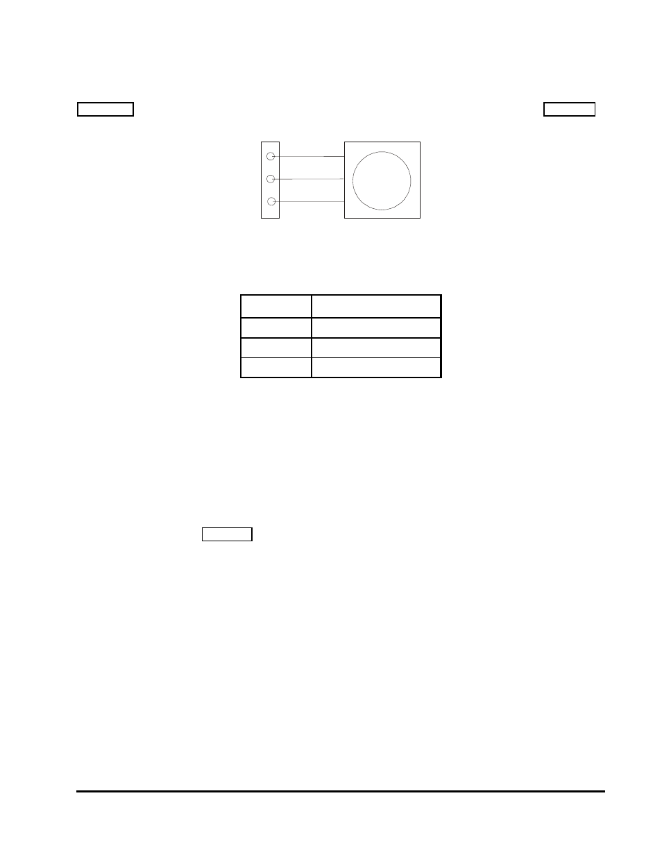
Fan Connector
Figure 2-3 shows the connection between the fan and J21. The pinout of J21 is shown in Table 2-5.
J21
5V CPU Fan
-
1
+
2
TACH
Figure 2-3. CPU Fan Connection (J21)
Table 2-5. Fan Power Connector (J21)
Pin #
Function
1
Switched Ground
2
+5V Power
3
TACH Output
System Memory
The module supports a single 168-pin DIMM socket. The system supports both 64-bit SDRAM and
72-bit SDRAM. The 72-bit SDRAM is used to support ECC (Error Detection And Correction). You
can install from 32MB to 256MB, depending on your memory needs.
The ROM BIOS automatically detects the size of the installed memory module and configures the
system accordingly at boot time (No jumpering or manual configuration is required.). The amount
of memory the BIOS measures can be displayed by running Setup. Memory error correction (ECC)
is supported by the chip set used on the Little Board P6d module. DRAM memory is allocated in
the system as shown in Table 2-6.