Ampro Corporation LITTLE BOARD 5001451A User Manual
Page 42
2-24
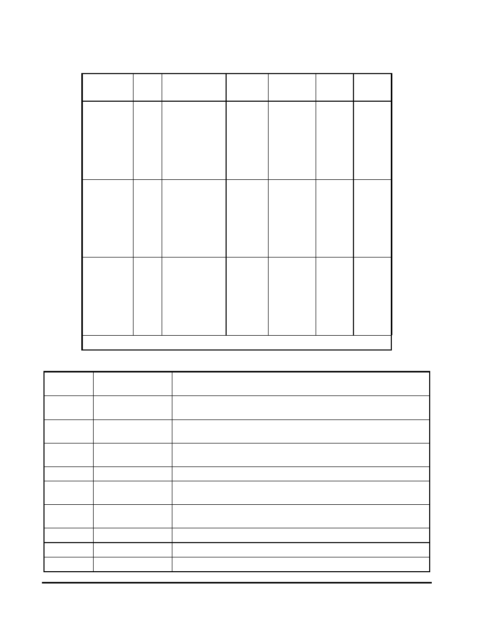
Table 2-22. Parallel Port Register Bits
Register
Bit
Signal Name
or Function
In/Out
Active
High/Low
J5
Pin
DB25F
Pin
DATA
(378h)
0
1
2
3
4
5
6
7
PD 0
PD 1
PD 2
PD 3
PD 4
PD 5
PD 6
PD 7
I/O
I/O
I/O
I/O
I/O
I/O
I/O
I/O
High
High
High
High
High
High
High
High
6
10
14
18
22
26
30
34
2
3
4
5
6
7
8
9
STATUS
(379h)
0
1
2
3
4
5
6
7
TMOUT
0
0
ERROR*
SLCT
PE
ACK* (IRQ)
BUSY
In
---
---
In
In
In
In
In
---
---
---
Low
High
High
Low
High
---
---
---
8
50
46
38
42
---
---
---
15
13
12
10
11
CONTROL
(37Ah)
0
1
2
3
4
5
6
7
STB*
AUTOFD*
INIT*
SELIN*
IRQE
PCD
1
1
Out*
Out*
Out*
Out*
---
---
---
---
Low
Low
High
High
High
High
---
---
2
4
12
16
---
---
---
---
1
14
16
17
---
---
---
---
Note: * Can also be used as input (see text).
Table 2-23. Standard and PS/2 Mode Register Bit Definitions
Signal
Name
Full Name
Description
TMOUT
Time-out
Valid only in EPP mode , this signal goes true after a 10
µ
S time-
out has occurred on the EPP bus. This bit is cleared by reset.
ERR*
Error
Reflects the status of the -ERROR input. 0 means an error has
occurred.
SLCT
Printer selected
status
Reflects the status of the SLCT input. 1 means a printer is on-line.
PE
Paper end
Reflects the status of the PE input. 1 indicates paper end.
ACK*
Acknowledge
Reflects the status of the ACK input. 0 indicates a printer received
a character..
BUSY*
Busy
Reflects the complement of the BUSY input. 0 indicates a printer
is busy.
STB*
Strobe
This bit is inverted and output to the -STROBE pin.
AUTOFD
Auto feed
This bit is inverted and output to the -AUTOFD pin.
INIT*
Initiate output
This bit is output to the -INIT pin.