2 boost stage design steps, An372 – Cirrus Logic AN372 User Manual
Page 28
AN372
28
AN372REV1
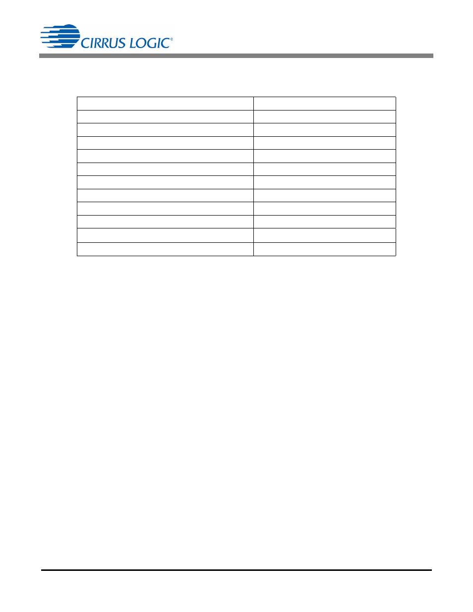
Step 13) Buck Inductor Specification
Specifications for the buck inductor L4 can now be compiled to enable suppliers to design within size and cost
constraints.
Step 14) Circuit Adjustments
Now that the inductor has been defined and built, it may need to be adjusted. For more information, see Circuit
Adjustments on page 15.
Validate that the system meets the operating criteria. This may require adjusting components like R
Sense
and
R
FBGAIN
. For more information, see Recalculate R
4.2 Boost Stage Design Steps
Using Equation 23, calculate I
PK(BST)
:
Using Equation 24, calculate R
IPK
:
Step 17) Boost Inductor Specifications
Use Figure 10 in the Boost Inductor Specifications section on page 19 to determine the boost value of the
boost inductance. Choosing a maximum switching frequency of 110kHz, find the intersection with the 230V
maximum switching curve, and get the corresponding power. This is 50 Watt
mH, the constant (P
IN
L
BST
),
for this frequency and voltage. Dividing by the input power, obtain the inductor value.
Parameter
Value
Output DC Power
10.1W
Converter Topology
CRM Buck
Switching Frequency
125kHz
Primary Inductance
3.8 mH
10%
Peak Current in the (N+1) Turn Winding
0.207A
RMS Current in the N-turn Winding
62mA
Turn Ratio N:1
4
RMS Current in the 1-turn Winding
0.511A
Leakage Inductance with 1-turn Winding Shorted
<50
H
Auxiliary Winding Turn Ratio (N/N
AUX
)
20
Auxiliary Wire
Any convenient gauge
I
PK BST
3.64 P
IN
V
RMS
---------------------------
3.64 10.1W
230V
-----------------------------------
160mA
=
=
=
[Eq. 60]
R
IPK
15.625 10
3
V
I
PK BST
-------------------------------------------
15.625 10
3
V
160mA
-------------------------------------------
97.6k
=
=
=
[Eq. 61]
L
BST
50WmH
P
IN
----------------------
50WmH
10.1W
----------------------
5mH
=
=
=
[Eq. 62]