An372 – Cirrus Logic AN372 User Manual
Page 18
AN372
18
AN372REV1
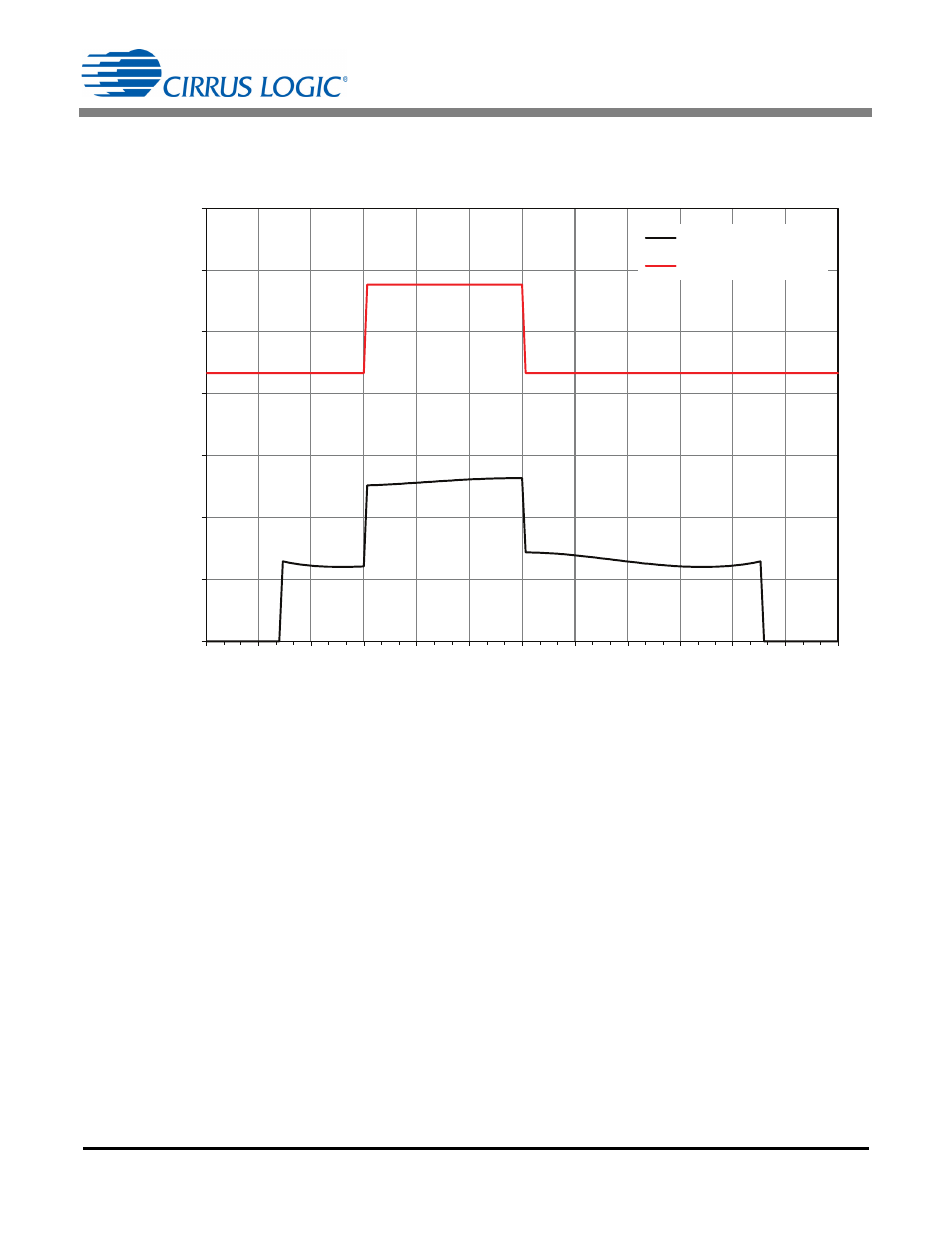
The AC line current does not follow the inductor peak current envelope because the circuit operates in CRM
and DCM. The switching frequency and duty cycle changes across the AC line phase resulting in a changing
average value after the EMI filter smoothing.
Once I
PK(BST)
is determined, R
IPK
must be calculated. I
PK(BST)
sets the maximum value for the internal source
drive current sink, which is equal to I
PK(BST)
. See Equation 24:
During circuit adjustment, connect an electronic load in CV mode for testing and clamp protection. Set the
electronic load so that the boost output voltage is 425V for a 230V system or 215V for a 120V system.
Measure switching frequency at a fixed V
rect
voltage. Adjust I
PK(BST)
to obtain the desired waveform at the mid
voltage, as shown in Figure 9.
Step 17) Boost Inductor Specifications
The CS1612/13 controls I
PK(BST)
and keeps the boost stage operating in CRM. The boost inductance L
BST
only controls the average switching frequency. The instantaneous frequency changes to meet the I
PK(BST)
imposed by the controller and the duty cycle imposed by the CRM/DCM algorithm.
The boost inductor should be designed for 600mA at 3000Gauss. For a given input voltage design, the product
of (L
BST
P
IN
) is constant. Choose the frequency range on Figure 10 to find the corresponding (L
BST
P
IN
)
product, and divide the product by P
IN
to obtain L
BST
.
0.00
0.02
0.04
0.06
0.08
0.10
0.12
0.14
0
15
30
45
60
75
90
105
120
135
150
165
180
Cur
rent (A
)
Phase Angle (°)
AC Line Current
Inductor Peak Current
Figure 9. Current vs Phase Angle
[Eq. 24]
R
IPK
15.625 10
3
V
I
PK BST
-------------------------------------------
=