Design considerations, 1 twisted pair interface, 2 100base-fx interface – Cirrus Logic CS8952 User Manual
Page 62: 1 twisted pair interface 7.2 100base-fx interface, Cs8952
CS8952
CrystalLAN™ 100BASE-X and 10BASE-T Transceiver
62
DS206F1
7. DESIGN CONSIDERATIONS
The CS8952 is a mixed-signal device containing
the high-speed digital and analog circuits required
to implement Fast Ethernet communication. It is
important the designer adhere to the following
guidelines and recommendations for proper and re-
liable operation of the CS8952. These guidelines
will also benefit the design with good EMC perfor-
mance.
7.1
Twisted Pair Interface
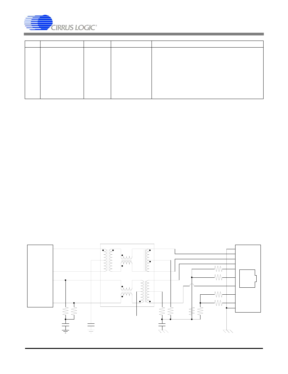
The recommended connection of the twisted-pair
interface is shown if Figure 6. The unused cable
pairs are terminated to increase the common-mode
performance. Common-mode performance is also
improved by connecting the center taps of the RX
and TX input circuits to the DC-isolated ground
plane. The 0.01 µF capacitor C1 must provide 2 kV
(1,500 Vrms for 60 seconds) of isolation to meet
802.3 requirements. If a shielded RJ45 connector is
used (recommended), the shield should be connect-
ed to chassis ground.
7.2
100BASE-FX Interface
Figure 7 shows the recommended connection for a
100BASE-FX interface to a Hewlett-Packard
HFBR-5103 fiber transceiver. Termination circuit-
ry may need to be revised for other fiber transceiv-
ers. The FX Drive bit in the Loopback, Bypass, and
Receiver Error Mask Register (address 18h) may
be used to tailor the PECL interface for 50
Ω or
150
Ω loads.
0
Jabber Enable
Read/Write 1
When set, the jabber function is enabled. When
clear, and if the CS8952 is in 10BASE-T full-duplex
or 10BASE-T ENDEC loopback mode, the jabber
function is disabled.
Note: When the National Compatibility Mode bit (bit
7) is set, the Jabber function may also be disabled
for 10BASE-T half-duplex, although this is not rec-
ommended.
BIT
NAME
TYPE
RESET
DESCRIPTION
49.9
Ω
49.9
Ω
0.1 µF
0.1 µF
CS8952
TX+
TX-
RX+
RX-
80
81
91
92
NC
16
15
2
1
14
3
10
11
6
7
12
T1
TG22-3506
5
51
Ω
75
Ω
0.01 µF
75
Ω
51
Ω
51
Ω
51
Ω
51
Ω
1
2
3
4
5
6
7
8
RJ-45
SHLD
SHLD
2KV
51
Ω
Figure 6. Recommended Connection of Twisted-Pair Ports (Network Interface Card)