5 mii management frame structure, 4 illustrates, Errors, and figure 5 illustrates – Cirrus Logic CS8952 User Manual
Page 28: Cs8952
CS8952
CrystalLAN™ 100BASE-X and 10BASE-T Transceiver
28
DS206F1
specification, while the remaining registers provide
enhanced monitoring and control capabilities.
As many as 31 devices may share a single Manage-
ment Interface. A unique five-bit PHY address is
associated with each device, with all devices re-
sponding to PHY address 00000. The CS8952 de-
termines its PHY address at power-up or reset
through the PHYAD[4:0] pins.
4.5
MII Management Frame Structure
Frames transmitted through the MII Management
Interface have the following format (Table 6):
When the management interface is idle, the MDIO
signal will be tri-stated, and the MAC is required to
keep MDIO pulled to a logic ONE.
At the beginning of each transaction, the MAC will
typically send a sequence of 32 contiguous logic
ONE bits on MDIO with 32 corresponding clock
cycles on MDC to provide the CS8952 with a pat-
tern that it can use to establish synchronization.
Optionally, the CS8952 may be configured to oper-
ate without the preamble through bit 9 of the PCS
Sub-Layer Configuration Register (address 17h).
The Start of Frame is indicated by a 01 bit pattern.
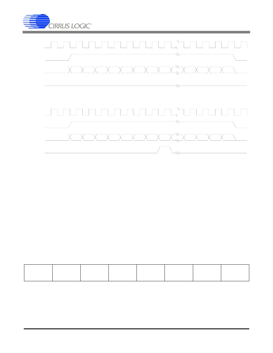
TX_CLK
TX_EN
TXD[3:0]
TX_ER
Preamble/SFD
DATA
Figure 4. Transmission without errors
TX_CLK
TX_EN
TXD[3:0]
TX_ER
Preamble/SFD
DATA
HALT
Figure 5. Transmission with errors
Preamble
(32 bits)
Start of
Frame
(2 bits)
Opcode
(2 bits)
PHY
Address
(5 bits)
Register
Address
(5 bits)
Turnaround
(2 bits)
Data
(16 bits)
Idle
Table 6. Format for Frame Transmitted through the MII Management Interface