Leds, 10base-t interface, 10base-2 and aui interfaces – Cirrus Logic AN83 User Manual
Page 18: Logic schematics, Figure 8. 10base-t schematic 3.3v, An83
AN83
18
AN83REV3
PROM is not necessary for the CS8900A, and the
CS8900A will respond to IO addresses 0300h
through 030Fh after a reset.
Please refer to the CS8900A data sheet for informa-
tion about programming the EEPROM. Please re-
fer to “JUMPERLESS DESIGN” on page 45 of
this document for information about EEPROM in-
ternal word assignments.
LEDs
Many embedded systems do not require LEDs for
the Ethernet traffic. Therefore this reference de-
sign does not implement any LEDs. However, the
CS8900A has direct drives for the three LEDs.
Please refer to the data sheet for the CS8900A for a
description of the LED functions available on the
CS8900A.
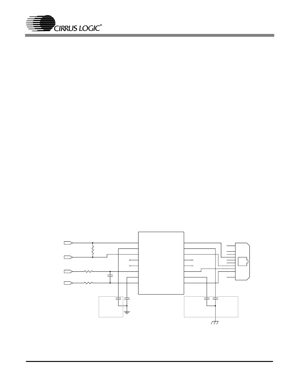
10BASE-T Interface
The 10BASE-T interface for the CS8900A is
straight forward. Please refer to Figure 8 (3.3V)
and Figure 10 (5V) for connections and compo-
nents of this circuit. Transmit and receive signal
lines from the CS8900A are connected to an isola-
tion transformer at location T1. This isolation
transformer has a 1:1 ratio between the primary and
the secondary windings on the receive side. It has
a 1:
√2 (1:1.414) ratio between the primary and the
secondary windings for the transmit lines for 5V
operation or a ratio of 1:2.5 for 3.3V operation. Re-
sistor R1 provides termination for the receive lines.
Resistors R2 and R3 are in series with the differen-
tial pair of transmit lines for impedance matching.
10BASE-2 and AUI Interfaces
As many embedded systems require only a
10BASE-T interface, this reference design imple-
ments only the 10BASE-T interface. However,
should a user require a 10BASE-2 or AUI inter-
face, the CS8900A provides a direct interface to the
AUI. Please refer to “Low Cost Ethernet Combo
Card Reference Design: CRD8900” on page 21 of
this document for details about the AUI interface.
Logic Schematics
Figures 8, 9 and 10 detail the logic schematics for
the various circuits used in the reference design.
10BT_RD-
100
R2
8
R4
8
R5
.1uF
.1uF
C23
.1uF 2KV
C28
.1uF 2KV
C29
1
1
2
2
3
3
4
4
5
5
6
6
7
7
8
8
1
2
3
4
5
6
7
8
16
(1-3) (16-14) 1:1
(6-8) (11-9) 1:2.5
10BaseT Transformer
15
14
13
12
11
10
10
J21
9
16
15
14
13
12
11
10
9
9
Do Not
Populate
560pF
C30
10BT_RD+
10BT_TD-
10BT_TD+
Do Not
Populate
Figure 8. 10BASE-T Schematic 3.3V