Auto-boot mode using e2prom, 1 auto-boot configuration, 2 auto-boot data for e2prom – Cirrus Logic CS5461A User Manual
Page 38: 3 suggested e2prom devices, Auto-boot mode using e, 1 auto-boot configuration 8.2 auto-boot data for e, 3 suggested e, Figure 14. typical interface of e, Cs5461a, Prom
CS5461A
38
DS661F3
8. AUTO-BOOT MODE USING E
2
PROM
When the CS5461A MODE pin is asserted (logic 1), the
CS5461A auto-boot mode is enabled. In auto-boot
mode, the CS5461A downloads the required com-
mands and register data from an external serial
E
2
PROM, allowing the CS5461A to begin performing
energy measurements.
8.1 Auto-Boot Configuration
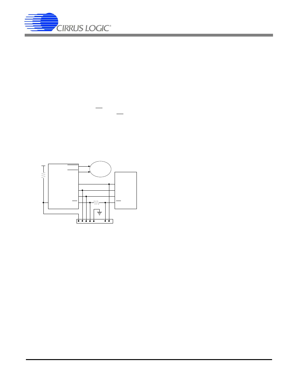
A typical auto-boot serial connection between the
CS5461A and a E
2
PROM is illustrated in
. In
auto-boot mode, the CS5461A’s CS and SCLK are con-
figured as outputs. The CS5461A asserts CS, provides
a clock on SCLK, and sends a read command to the
E
2
PROM on SDO. The CS5461A reads the user-speci-
fied commands and register data presented on the SDI
pin. The E
2
PROM’s programmed data is utilized by the
CS5461A to change the designated registers’ default
values and begin registering energy.
Figure 14 also shows the external connections that
would be made to a calibrator device, such as a PC or
custom calibration board. When the metering system is
installed, the calibrator would be used to control calibra-
tion and/or to program user-specified commands and
calibration values into the E
2
PROM. The user-specified
commands/data will determine the CS5461A’s exact
operation, when the auto-boot initialization sequence is
running. Any of the valid commands can be used.
8.2 Auto-Boot Data for E
2
PROM
Below is an example code set for an auto-boot se-
quence. This code is written into the E
2
PROM by the us-
er. The serial data for such a sequence is shown below
in single-byte, hexidecimal notation:
- 40 00 00 61
Write Configuration Register, turn high-pass filters
on, set K=1.
- 44 7F C4 A9
Write value of 0x7FC4A9 to Current Gain
Register.
- 48 FF B2 53
Write value of 0xFFB253 to Voltage Gain
Register.
- 4C 00 7D 00
Set PulseRateE
1,2
Register to 1000 Hz.
- 74 00 00 04
Unmask bit #2 (LSD) in the Mask Register).
- E8
Start continuous conversions
- 78 00 01 00
Write STOP bit to Control Register, to terminate
auto-boot initialization sequence.
8.3 Suggested E
2
PROM Devices
Several industry-standard, serial E
2
PROMs that will
successfully run auto-boot with the CS5461A are listed
below:
•
Atmel AT25010, AT25020 or AT25040
•
National Semiconductor NM25C040M8 or NM25020M8
•
Xicor X25040SI
These types of serial E
2
PROMs expect a specific 8-bit
command (00000011) in order to perform a memory
read. The CS5461A has been hardware programmed to
transmit this 8-bit command to the E
2
PROM at the be-
ginning of the auto-boot sequence.
Figure 14. Typical Interface of E
2
PROM to CS5461A
CS5461A
EEPROM
EOUT1
EOUT2
MODE
SCLK
SDI
SDO
CS
SCK
SO
SI
CS
Connector to Calibrator
VD+
5 K
5 K
Mech. Counter
Stepper Motor
or