2 alternate pulse format, 3 mechanical counter format, 4 stepper motor format – Cirrus Logic CS5461A User Manual
Page 17: Figure 4. alternate pulse format on e1, Figure 5. mechanical counter format on e1, Cs5461a, E1 positive energy negative energy
CS5461A
DS661F3
17
is (MCLK/K)/16. The pulse duration (t
dur
) is an integer
multiple of MCLK cycles, approximately equal to:
The maximum pulse duration (t
dur
) is determined by the
sampling rate and the minimum is defined by the maxi-
mum pulse frequency. The t
dur
limits are:
The Pulse Width Register (PW) does not affect the nor-
mal format.
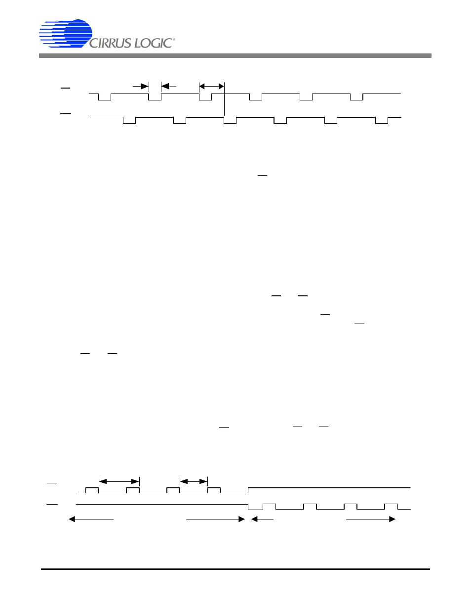
5.4.2 Alternate Pulse Format
Setting bits MECH = 1 and STEP = 0 in the Control
Register and ALT = 1 in the Configuration Register con-
figures the E1 and E2 pins for alternating pulse format
output (see
). Each pin produces alternating ac-
tive-low pulses with a pulse duration (t
PW
) defined by
the Pulse Width Register (PW):
If MCLK = 4.096 MHz, K = 1, and PW = 1 then
t
PW
= 0.25 ms. To ensure that pulses occur on the E1
and E2 output pins when full-scale input signals are ap-
plied to the voltage and current channels, then:
The pulse frequency (FREQ
E
) is determined by the
PulseRateE
1,2
Register and can be calculated using the
transfer function. The energy direction is not defined in
the alternate pulse format.
5.4.3 Mechanical Counter Format
Setting bits MECH = 1 and STEP = 0 in the Control
Register and bit ALT = 0 in the Configuration Register
enables E1 and E2 for mechanical counters and similar
discrete counting instruments. When energy is nega-
tive, pulses appear on E2 (see Figure 5). When energy
is positive, the pulses appear on E1. The pulse width is
defined by the Pulsewidth Register and will limit the out-
put pulse frequency (FREQ
E
). By default, PW = 512
samples, if MCLK = 4.096 MHz and K = 1 then
t
PW
= 128 ms. To ensure that pulses will occur, the
PulseRateE
1,2
Register must be set to an appropriate
value.
5.4.4 Stepper Motor Format
Setting bits STEP = 1 and MECH = 0 in the Control
Register and bit ALT = 0 in the Configuration Register
configures the E1 and E2 pins for stepper motor format.
When the accumulated active power equals the defined
t
dur
sec
1
PulseRateE
1 2
,
8
--------------------------------------------
1
(MCLK/K)/16
8
-----------------------------------
t
dur
sec
1
(MCLK/K)/1024
8
-----------------------------------------
Figure 4. Alternate Pulse Format on E1 and E2
E1
...
...
E2
...
...
...
t
PW
FREQ
E
t
PW
ms
PW
(MCLK/K)/1024
-----------------------------------------
=
PulseRateE
1 2
,
1
t
PW
------------
t
PW
E1
Positive Energy
Negative Energy
...
...
...
...
E2
FREQ
E
Figure 5. Mechanical Counter Format on E1 and E2