12 event handler, 1 typical interrupt handler, Table 3. interrupt configuration – Cirrus Logic CS5461A User Manual
Page 21: Cs5461a
CS5461A
DS661F3
21
dal inputs so there are no problems with slow edge
times.
The CS5461A can be driven by an external oscillator
ranging from 2.5 to 20 MHz, but the K divider value must
be set such that the internal MCLK will run somewhere
between 2.5 MHz and 5 MHz. The K divider value is set
with the K[3:0] bits in the Configuration Register. As an
example, if XIN = MCLK = 15 MHz, and K is set to 5,
then DCLK is 3 MHz, which is a valid value for DCLK.
5.12 Event Handler
The INT pin is used to indicate that an internal error or
event has taken place in the CS5461A. Writing a logic 1
to any bit in the Mask Register allows the corresponding
bit in the Status Register to activate the INT pin. The in-
terrupt condition is cleared by writing a logic 1 to the bit
that has been set in the Status Register.
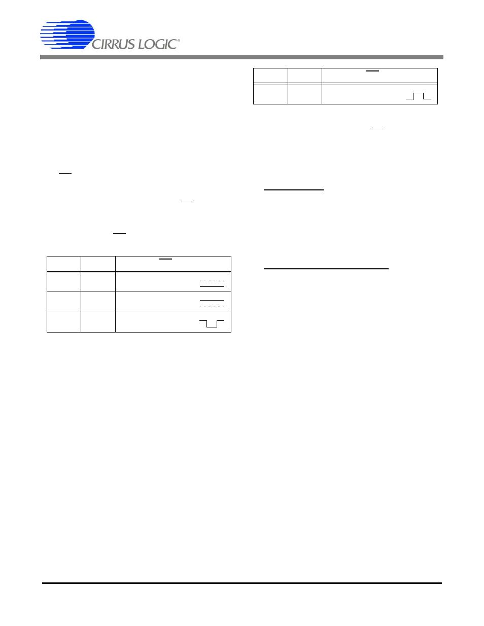
The behavior of the INT pin is controlled by the IMODE
and IINV bits of the Configuration Register.
If the interrupt output signal format is set for either falling
or rising edge, the duration of the INT pulse will be at
least one DCLK cycle (DCLK = MCLK/K).
5.12.1 Typical Interrupt Handler
The steps below show how interrupts can be handled.
INITIALIZATION:
1) All Status bits are cleared by writing 0xFFFFFF to
the Status Register.
2) The condition bits which will be used to generate
interrupts are then set to logic 1 in the Mask Reg-
ister.
3) Enable interrupts.
INTERRUPT HANDLER ROUTINE:
4) Read the Status Register.
5) Disable all interrupts.
6) Branch to the proper interrupt service routine.
7) Clear the Status Register by writing back the read
value in step 4.
8) Re-enable interrupts.
9) Return from interrupt service routine.
IMODE
IINV
INT Pin
0
0
Active-low Level
0
1
Active-high Level
1
0
Low Pulse
Table 3. Interrupt Configuration
1
1
High Pulse
IMODE
IINV
INT Pin
Table 3. Interrupt Configuration