Cs5461a – Cirrus Logic CS5461A User Manual
Page 29
CS5461A
DS661F3
29
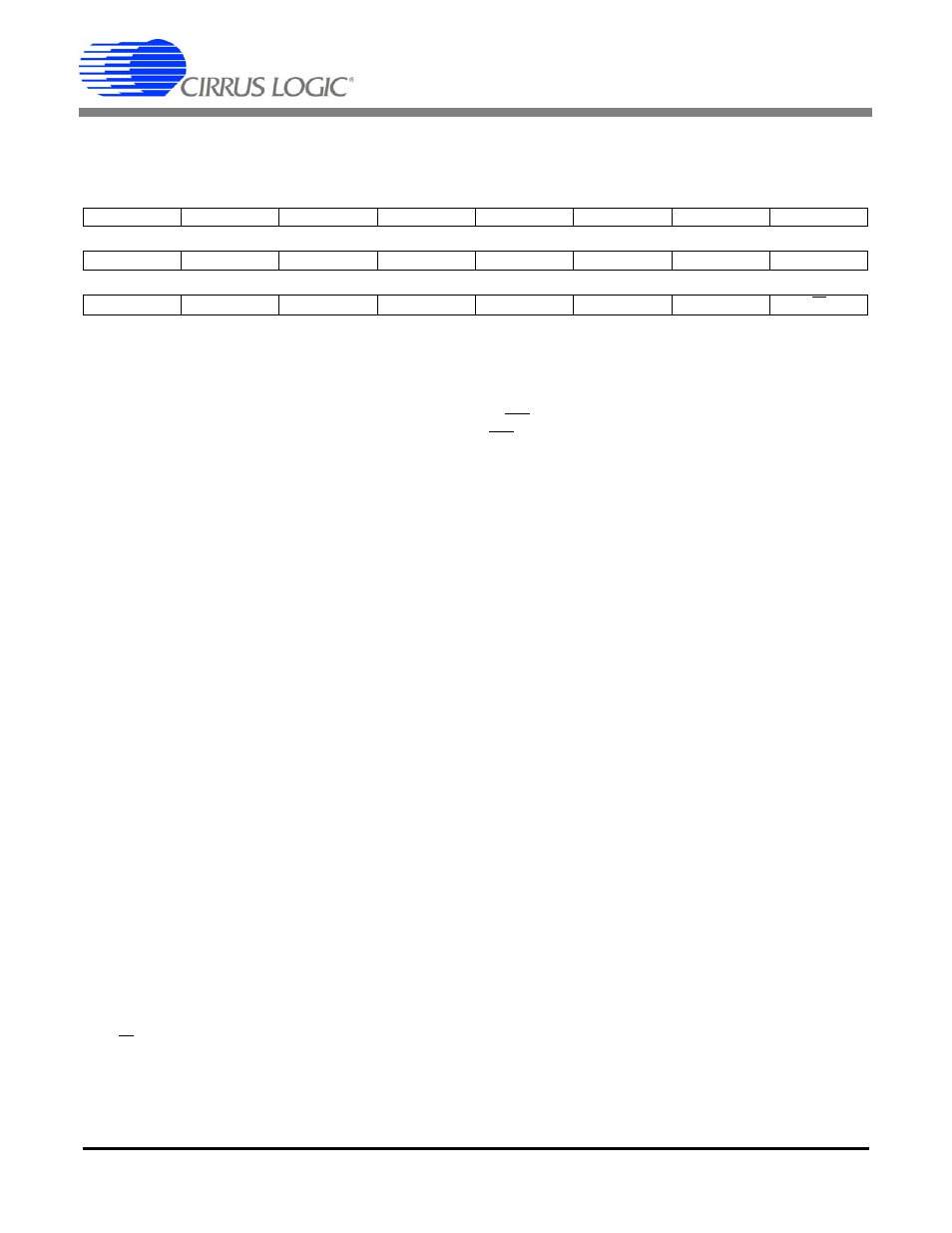
6.10 Status Register and Mask Register ( Status , Mask )
Address: 15 (Status); 26 (Mask)
Default =
0x000001 (Status Register), 0x000000 (Mask Register)
The Status Register indicates status within the chip. In normal operation, writing a '1' to a bit will cause the bit
to reset. Writing a '0' to a bit will not change it’s current state.
The Mask Register is used to control the activation of the INT pin. Placing a logic '1' in a Mask bit will allow the
corresponding bit in the Status Register to activate the INT pin when the status bit is asserted.
DRDY
Data Ready. During conversions, this bit will indicate the end of computation cycles. For cali-
brations, this bit indicates the end of a calibration sequence.
CRDY
Conversion Ready. Indicates a new conversion is ready. This will occur at the output word rate.
IOR
Current Out of Range. Set when the Instantaneous Current Register overflows.
VOR
Voltage Out of Range. Set when the Instantaneous Voltage Register overflows.
IROR
I
RMS
Out of Range. Set when the I
RMS
Register overflows.
VROR
V
RMS
Out of Range. Set when the V
RMS
Register overflows.
EOR
Energy Out of Range. Set when P
ACTIVE
overflows.
TUP
Temperature Updated. Indicates the Temperature Register has updated.
TOD
Modulator oscillation detected on the temperature channel. Set when the modulator oscillates
due to an input above full scale.
VOD (IOD)
Modulator oscillation detected on the voltage (current) channel. Set when the modulator oscil-
lates due to an input above full scale. The level at which the modulator oscillates is significantly
higher than the voltage (current) channel’s differential input voltage range.
Note:
The IOD and VOD bits may be ‘falsely’ triggered by very brief voltage spikes from the
power line. This event should not be confused with a DC overload situation at the in-
puts, when the IOD and VOD bits will re-assert themselves even after being cleared,
multiple times.
LSD
Low Supply Detect. Set when the voltage at the PFMON pin falls below the low-voltage thresh-
old (PMLO), with respect to AGND pin. The LSD bit cannot be reset until the voltage at PFMON
pin rises back above the high-voltage threshold (PMHI).
VSAG
Indicates a voltage sag has occurred.
See Section 5.5 Voltage Sag-detect Feature
IC
Invalid Command. Normally logic 1. Set to logic 0 if an invalid command is received or the Sta-
tus Register has not been successfully read.
23
22
21
20
19
18
17
16
DRDY
CRDY
IOR
VOR
15
14
13
12
11
10
9
8
IROR
VROR
EOR
7
6
5
4
3
2
1
0
TUP
TOD
VOD
IOD
LSD
VSAG
IC