Cirrus Logic CS5461A User Manual
Features, Description, Prom. • power supply configurations
Copyright
Cirrus Logic, Inc. 2011
(All Rights Reserved)
CS5461A
Single Phase, Bi-directional Power/Energy IC
Features
• Energy Data Linearity: ±0.1% of Reading over
1000:1 Dynamic Range
• On-chip Functions:
- Instantaneous Voltage, Current, and Power
- I
RMS
and V
RMS
, Apparent and Active (Real) Power
- Energy-to-pulse Conversion for Mechanical
Counter/Stepper Motor Drive
- System Calibrations and Phase Compensation
- Temperature Sensor
- Voltage Sag Detect
• Meets Accuracy Spec for IEC, ANSI, & JIS.
• Low Power Consumption
• Current Input Optimized for Sense Resistor.
• GND-referenced Signals with Single Supply
• On-chip 2.5 V Reference (25 ppm/°C typ)
• Power Supply Monitor
• Simple Three-wire Digital Serial Interface
• “Auto-boot” Mode from Serial E
2
PROM.
• Power Supply Configurations:
VA+ = +5 V; AGND = 0 V; VD+ = +3.3 V to +5 V
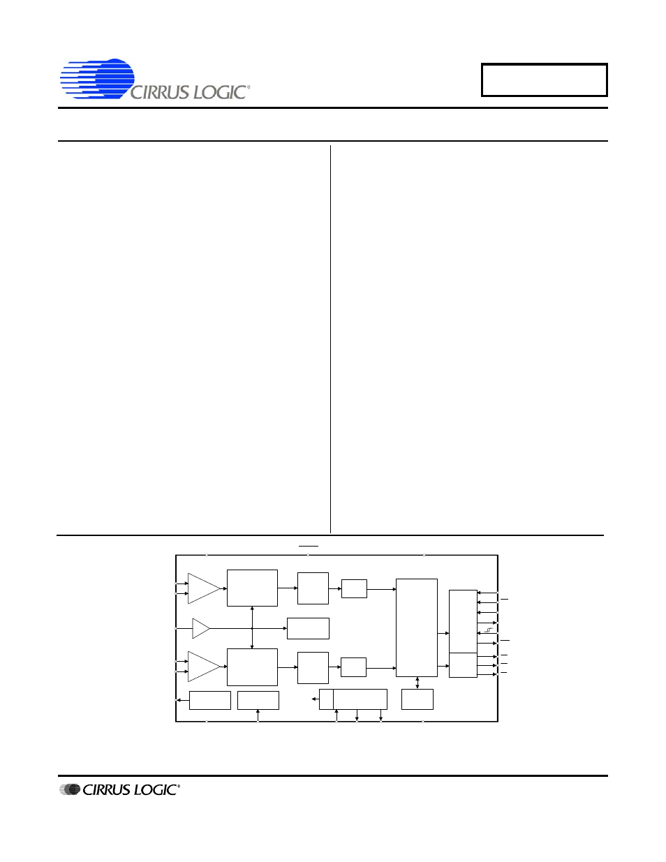
Description
The CS5461A is an integrated power measure-
ment device which combines two
analog-to-digital converters, power calculation
engine, energy-to-frequency converter, and a
serial interface on a single chip. It is designed to
accurately measure instantaneous current and
voltage, and calculate V
RMS
, I
RMS
, instanta-
neous power, apparent power, and active power
for single-phase, 2- or 3-wire power metering
applications.
The CS5461A is optimized to interface to shunt
resistors or current transformers for current mea-
surement, and to resistive dividers or potential
transformers for voltage measurement.
The CS5461A features a bi-directional serial in-
terface for communication with a processor, and
a programmable energy-to-pulse output func-
tion. Additional features include on-chip
functionality to facilitate system-level calibration,
temperature sensor, voltage sag detection, and
phase compensation.
ORDERING INFORMATION:
See
VA+
VD+
IIN+
IIN-
VIN+
VIN-
VREFIN
VREFOUT
AGND
XIN
XOUT CPUCLK
DGND
CS
SDO
SDI
SCLK
INT
Voltage
Reference
System
Clock
/K
Clock
Generator
Serial
Interface
E-to-F
Power
Monitor
PFMON
x1
RESET
Digital
Filter
Calibration
MODE
Power
Calculation
Engine
4th Order
Modulator
2nd Order
Modulator
Temperature
Sensor
Digital
Filter
PGA
HPF
Option
HPF
Option
E1
E2
E3
x10
APR ‘11
DS661F3
Document Outline
- Features & Description
- Table of Contents
- List of Figures
- List of Tables
- 1. Overview
- 2. Pin Description
- 3. Characteristics & Specifications
- 4. Theory of Operation
- 5. Functional Description
- 5.1 Analog Inputs
- 5.2 High-pass Filters
- 5.3 Performing Measurements
- 5.4 Energy Pulse Output
- 5.5 Voltage Sag-detect Feature
- 5.6 No Load Threshold
- 5.7 On-chip Temperature Sensor
- 5.8 Voltage Reference
- 5.9 System Initialization
- 5.10 Power-down States
- 5.11 Oscillator Characteristics
- 5.12 Event Handler
- 5.13 Serial Port Overview
- 5.14 Commands
- 6. Register Description
- 7. System Calibration
- 8. Auto-boot Mode Using E2PROM
- 9. Basic Application Circuits
- 10. Package Dimensions
- 11. Ordering Information
- 12. Environmental, Manufacturing, & Handling Information
- 13. Revision History