5 programming the on-board serial flash, 2 changing serial control protocol (i, 5 programming the on-board serial flash -8 – Cirrus Logic CRD49530-USB User Manual
Page 33: Figure 4-10. crd49530 comm mode / memory usage -8, Or spi
Programming the On-board Serial Flash
CRD49530-USB User’s Manual
DS705RD3
Copyright 2008 Cirrus Logic
4-8
This dialog allows the user to set the following parameters for the CS4953xx Audio Output:
•
LRCLK polarity - Select the phase of LRCLK when the left-sample will be shifted out.
•
SCLK polarity - Select which edge of SCLK for which the output data will be valid.
•
DAO1/DAO2 - Select independent or unified clock domains for the DAO1 and DAO2 audio output
ports.
•
MCLK/SCLK Ratios - Select the ratio of LRCLK to MCLK, and LRCLK to SCLK.
4.4.2 Changing Serial Control Protocol (I
2
C
®
or SPI
™
) / Memory Usage
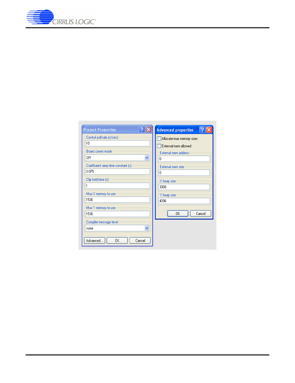
The CRD49530 is designed to communicate using either I
2
C or SPI protocols. In order to change the
communication mode in DSP Composer go to the menu bar and select File
Ö
Properties, which brings up
the Project Properties dialog. To configure Memory usage click on the Advanced button, as illustrated in
; Max memory allocation and external memory can be enabled from this panel.
Figure 4-10. CRD49530 Comm Mode / Memory Usage
4.5 Programming the On-board Serial Flash
The CRD49530 is populated with 4 Mbits of serial Flash that can be used to store custom DSP firmware
or run-time firmware configuration options. In order to emulate a system that boots the DSP from Flash,
the serial flash can be programmed in system with the desired DSP firmware. The host (the PC in this
case) can be used to perform a host-controlled master boot (HCMB) to boot the CS4953xx.
A special .uld file is loaded into the CS4953xx which provides the programming interface to the system
host. Programming then becomes a sequence of messages to the CS4953xx.
Please contact your local Cirrus representative for the Flash programming .uld file and the associated
application note.
§§