4 dai input, 4 dai input -6, Figure 4-7. crd49530 dai input properties -6 – Cirrus Logic CRD49530-USB User Manual
Page 31
Changing Audio Input Source
CRD49530-USB User’s Manual
DS705RD3
Copyright 2008 Cirrus Logic
4-6
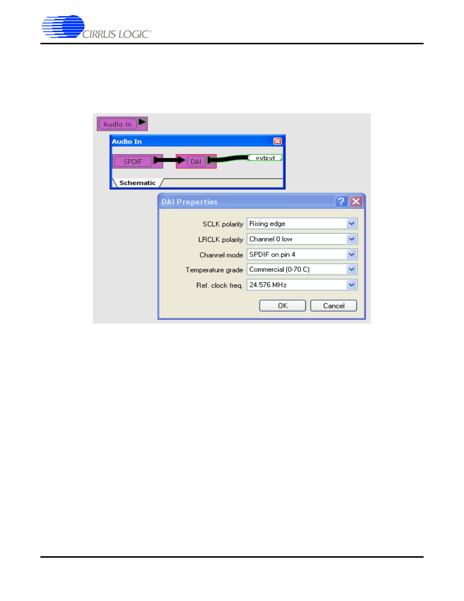
4.3.4 DAI Input
Each available audio source for the board is shown as a block connected to the DAI port of the CS4953xx
as illustrated in
. Right-clicking any of the sources and selecting Device Properties, produces
the DAI Properties dialog.
Figure 4-7. CRD49530 DAI Input Properties
This dialog allows the user to set the following parameters for the CS4953xx:
•
SCLK polarity - Rising edge / Falling edge
•
LRCLK polarity - Channel 0 low / Channel 0 high
•
Channel Mode - SPDIF on pin 4 / SPDIF on pin 0
•
Temperature Grade - CRD49530s are populated with commercial-grade chips by default
•
Ref Clock - Set to the frequency of the crystal driving the CS49353xx (Y1). This is the reference
clock is used to determine the clock dividers needed to derive Fs in ADC-only applications. If this
number changes, then all dividers for LRCLK/SCLK will change by the same ratio (e.g.
@24.576 MHz MCLK/512 = 1Fs = LRCLK, @12.288 MHz MCLK/256 = 1Fs = LRCLK)